A Musical Tesla Coil in the Singapore Science Center!
28.5 x 6.3in, CM300
IGBT H-bridge,
72kHz, >2m Sparks
DRSSTC 3
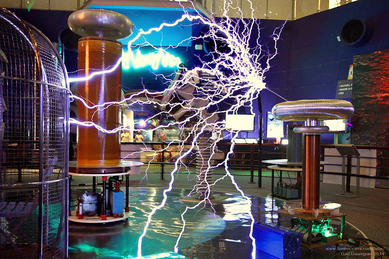
DRSSTC 3 attacks the bigger coil! - but no worries, no coil was
harmed :-) (680Apk, 180VAC)
DRSSTC 3 represents the largest and most powerful of the solid state
transistor tesla coils I've built over the past year (2013/14). In this project, I have tried to
incorporate many of the things I have learned in my previous table-top
DRSSTC 1 and medium DRSSTC 2 coils to produce
possibly one of the most compact and powerful
musical Tesla Coil in the South East Asian region. However, the goal of the project was not
to build the most powerful coil I could, but rather to build a coil with prudent choice
of components and using reasonable operating power supplies - i.e. the
result being a coil running at the limits of what one can draw from a
standard 15A 240V power outlet available in most homes, whilst still being easily
transportable.
After it was
constructed in Jan 2014, it evolved into a prototype project in
collaboration with the Singapore Science Centre, where some improvements
were made. Today, it resides as a exhibition in the main atrium,
accompanying the large spark-gap coil in the Tesla Coil cage, and is the
first publicly viewable musical coil in Singapore!
I hope this page will be a
resource for hobbyists around the world looking to build their own Tesla
Coil. I have described in detail the specifications of my coil for the
good of the community and you are free to use this design, and any
reference will be appreciated!
Thank you for visiting my page and if you have any questions, wish to
share your projects, or feel that my projects have inspired you in one
way or another, feel free to contact me at loneoceans[at]gmail(dot)com.
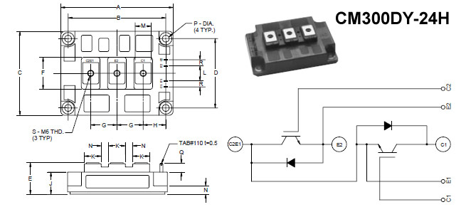
- CM300DU-24NFH 1200V 300A Full Bridge IGBT
inverter, set to a 700 Apk current limit
- 2kV 1uF x 2 Aerovox snubber capacitors
- FR4 Fiberglass and Aluminium laminated bus (1/16")
- 4700uF 450VDC Bus Capacitor x 2 in voltage doubler configuration
up to 240VAC in
- 375nF 10kV MMC 150A rms
- Modified UD2 driver with Primary Feedback and Phase Lead for ZVS
(~20-34 uH inductor)
- Flat Spiral Primary, 1/4" Copper Tubing, 9 turns tapped at 5.1-5.4 for
~75 to 72kHz
- 27.5 x 6.3" Secondary, 0.35mm, ~1850 turns, 79kHz
- 6" x 28.5" + 12.6" x 2" Toroids, Aluminium and PVC Ducting
- Designed for 240VAC input max for +-678VDC on the bus
Feel free to use this design as a reference for your
coil, but I would appreciate if you could credit this page if it has
helped your project :)
For much more videos and images of the coil in action, please scroll down to
Results!
Dec 2013
Introduction
Despite this being the most powerful tesla coil I have built,
it also turned out to be one of the most straightforward constructions
due to prior experience with my previous coils. However, its power and
size required care and attention to more details during
construction.
This page documents the general design, construction and results of this
project, as well as the general workings of DRSSTCs. For a more detailed
description of the nuances and operating principles, please refer to my
previous project pages.
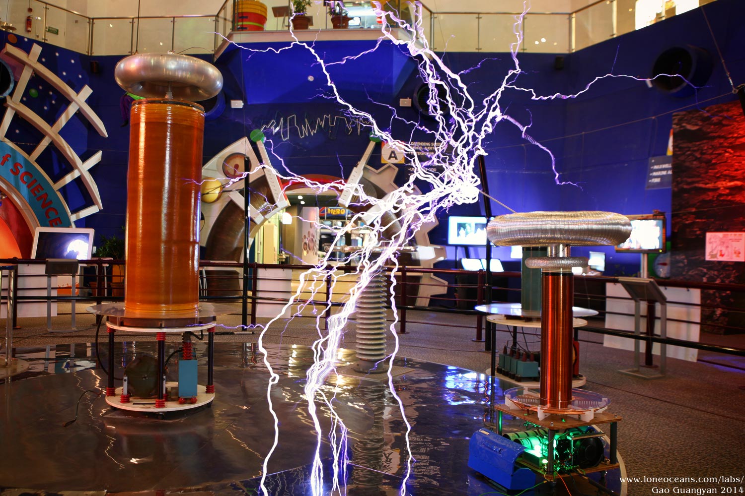
The motivation to build this coil was the desire to
create a compact master showpiece about 1.2m tall and generating sparks
in excess of 2m length. As of writing, the largest Tesla Coil in
Singapore seems to be the Tesla Technology Research Tesla Coil (a Model 9 variant) in the Singapore Science
Centre. Despite limited funding and resources, the goal of the project
was to produce a museum-worthy coil to rival the one in the Singapore
Science Centre, producing greater of equal spark output, whilst
remaining significantly smaller in size and half the input power albeit
still using a prudent choice of materials with a limited budget.
[Update Feb 2014] This project progressed well through the month of
January, where practically the entire coil was built over the course of the first 3
weeks of the month. However, a turn of events led to interest in the
project from the Singapore Science Centre, and the project evolved into
a collaborative one. In February, the completed coil
was moved to the Singapore Science Centre, where some modifications were
made in terms of reliability and better components. Thus DRSSTC 3 joins
the main spark gap Tesla Coil in the main exhibition atrium, as a
prototype of the very latest transistor tesla coils capable of playing
music.
General workings of a DRSSTC
SSTC are essentially a power inverter driving a coil at
its resonant frequency, typically via 100-1kV square waves. The most
common topology for implementing this is a conventional H-bridge of
half-bridge. Usually MOSFETs or IGBTs are use due to their high
switching speed and current handling capability. Some sort of feedback
is usually used to allow the coil to be self-tuning and thus resonant
automatically.
After the conventional SSTC was developed, hobbyists
around the world were in search of even greater spark output, leading to
the Double Resonant SSTC. The game plan is to not only make the
secondary a tuned circuit, but to also have a primary circuit tuned at
the same resonant frequency. When the primary coil is now driven by the
inverter at resonance, there is a far greater impedance match to the
secondary circuit. Due to resonant voltage rise, a much higher voltage
develops on the primary coil (to several kV). Since there is a greater
voltage, a much higher primary current can flow (several hundred amps),
creating much larger sparks on the secondary side. To prevent the
transistors from failing at such high peak currents, the coil is driven
in an interrupted fashion (several RF cycles, usually resulting
in several hundred us) at a time, each pulse being several ms apart. The
average duty cycle is therefore low, on the order of a few %. This
controller which interrupts the coil is known as an Interrupter.
In the case of DRSSTCs, IGBTs are often used instead of
MOSFETs due to their better high current handling capability. Recent
advances in technology have also brought the switching speed of these
transistors up, and their costs down. Therefore, IGBTs are now the
transistor of choice in the modern day DRSSTC.
In order for the operator to control the coil safely,
the interrupter is usually controlled via fiber optic from a control
box. The Pulse Width and repetition frequency can be controlled. In
order to produce music, the repetition frequency can be modulated based
on the desired tone. This is easily achieved via a microcontroller
interpreting MIDI signals, and converting them to rep frequency. E.g. an
“A” note will correspond to a 440Hz rep. frequency. The pulse width can
then be used to modulate the volume of the spark. The output sounds
harsh, but is unique in its own way.
Design Considerations & Schematics
Dec 2013
Building a large DRSSTC invariably involves the
use of large IGBTs. Although the price of IGBTs have dropped
significantly in the past few years in part due to their
popularity in electric vehicles, they are still very expensive
and form the bulk of the cost of the coil. With
limited resources, I had to work with what I had. Fortunately, I
managed to get some CM200 IGBTs. These are of the
standard brick-style and in the same line as the CM300s and
CM600s that have been known to work great in large DRSSTCs. As
such, the power capability of these IGBTs forms the upper limit
of the coil's power design. Eventually, the CM200s were replaced
with CM300s for greater reliability. Below outlines the process by which
the coil was designed.
Power and Size Considerations
The input power of the coil depends on several
factors, notably the frequency, running pulse widths, repetition
frequency as well as primary impedance. I knew from the
beginning that I wanted the coil to draw the maximum power I can
from frequently found sources. This places a single 15A 240VAC
output as an upper limit of 3600VA for the coil. The 15A line is
part a 30A ring system found in most homes, hence the coil
should also be able to run at the ballpark of 7200W peak via a
(relatively common 32A breaker. I also wanted the coil system to
be easily transportable in the boot of the car, and yet produce
impressive sparks exceeding 2m in length. With this in mind, I
decided to build a medium sized coil around 1.2m in total height
with a primary capacitor of 375nF running on voltage doubled
240V mains for 678VDC on the bus.
Inverter
The heart of this Tesla Coil is the inverter
which runs off a doubled 240VAC bus for +-678V across the
primary. However, I needed to choose the right transistor for
the coil. Some of the largest DRSSTCs built by coilers like
Steve Ward and Philip Slawinski uses the CM600 series brick
IGBTs, good for 600A, 1200Apk and produce 5m sparks with around
5 to 12kVA input. However, there are drawbacks to using CM600
including expensive cost, need for a very powerful and robust
gate driver, as well as low switching frequency in the ballpark
of 30kHz.
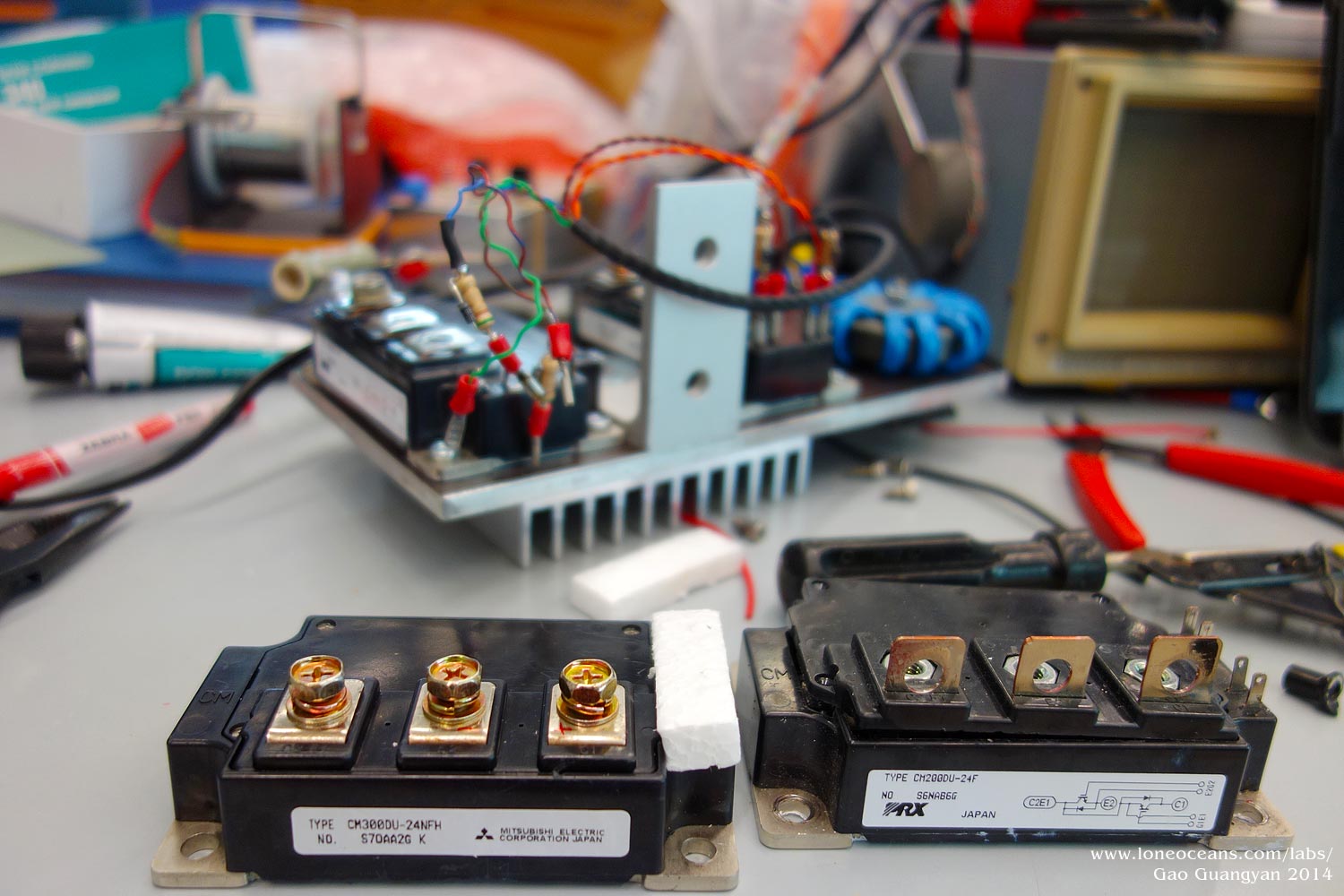
With the planned running power of around 3kVA,
it became clear the use of such IGBTs would be perhaps overkill and not necessary. Therefore the next best candidates were the famed
CM300 IGBTs, especially the latest NFH line rated at 300A at
60-70kHz or so. Regardless, these IGBTs modules were going for
around $100 used a piece, making them still quite expensive. In
the end, I decided to use CM200DU-24F IGBTs in a full bridge
configuration, transistors I already had on hand. Steve Ward has tested the CM300DY-24Hs extensively,
testing up to 5kApk at ZVS (zero voltage switching) before catastrophic failure.
Furthermore,
these IGBTs are known to run consistently well at 1500Apk if
switched correctly. With a 33% derating, it doesn't seem too far
fetched to push the CM200s at 1000Apk.
Eventually, to improve
reliability, these CM200 IGBTs were replaced with CM300DU-24NFH
IGBTs with the current limited set at 700Apk. They both have
the same footprint and package, making swaps with the previous
CM200s a simple task.
For reliable gate drive, I opted to use a simple
and proven Gate Drive Transformer (GDT) made using a large ferrite core. In addition,
feedback will be taken via two 1023:1 current transformers,
providing variable phase lead for tunable ZVS and OCD setting.
To reduce voltage spikes when switching, the bus caps will be
installed as closely as possible to the transistors via a
laminated bus. The bridge is then snubbed with 2uF 1kV snubber
capacitors bolted right on the IGBTs. The reasonably
low-inductance design and the 1200V rating should hopefully keep
the bridge running well and reliably.
Cooling is also essential. The IGBTs will be
mounted on a large heat plate. In order to move heat away as
quickly as possible from the system, I have opted for a thin
plate design with a strong fan actively blowing against the heat
sink fins to dissipate heat as quickly as possible. This is
opposed to using a large heat sink which will be good for short
runs, but may end up as a large thermal burden during longer
runs.
MMC
Because of the high RMS currents the resonant
capacitor will face, it is imperative to design one capable of
handling this enormous power. The standard practice is to use
the famed CDE 942 metal-film PP capacitors of the 1.5uF 2kV
variety. However, building a suitably sized bank will end up
costing hundreds of dollars. Instead (and I have to thank Bayley
for the suggestion), I managed to use some very nice pulse film
caps on eBay, each rated 580Vrms, 150Arms at 3.75uF.
Ten of
them in series provides a large but cheap and powerful MMC
capable of 150Arms at 375nF, and should have no problems at all
handling that power. As far as I know, these caps have been
tested by fellow coilers up to several kV each before soft
failures (like a typical PP film cap), so a 1kVDC rating each
should be in the ballpark per cap. In addition, they have been
used in other large coils and have shown excellent performance.
This gives me a fantastic 10kV 375nF bank to work with.
Components and Construction
Dec 2013 - Jan 2014
With the preliminary design done, it was time to begin building
the coil! Construction took place beginning at the end of
December through the 3rd week of January 2014. Some components
were later upgraded in mid Feb 2014.
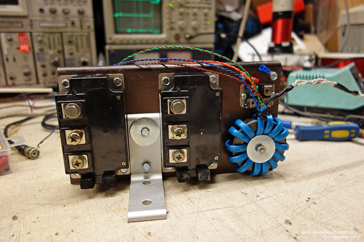
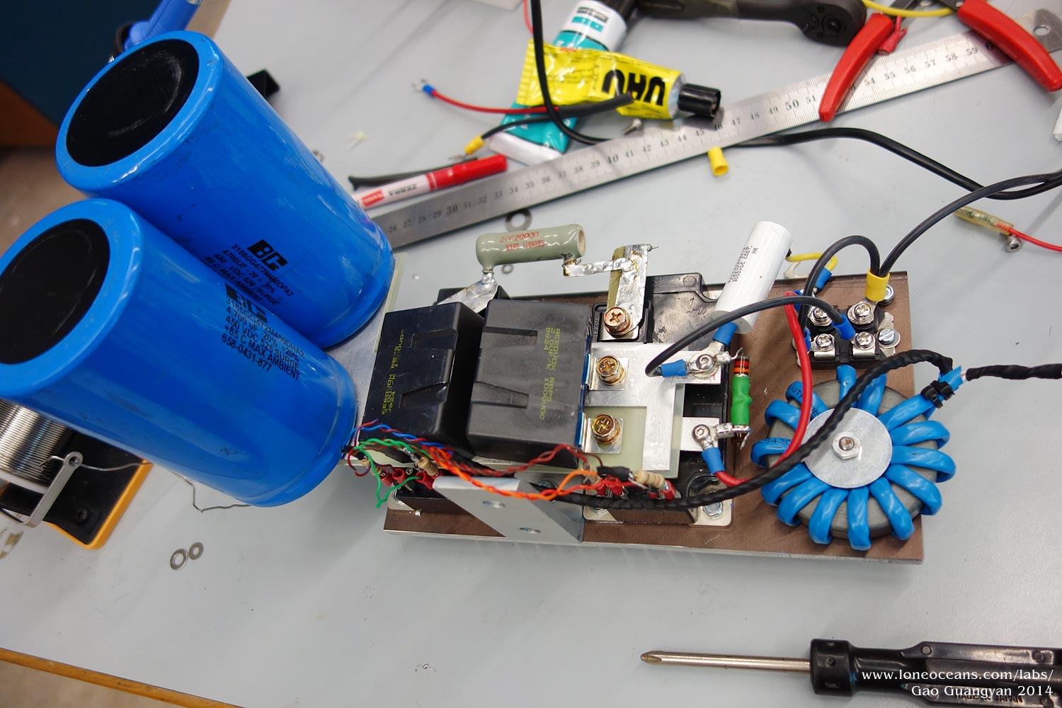
The Inverter
Building the inverter was straightforward and took one afternoon
of work. An aluminum heat sink was drilled and tapped to accept
two of the CM200 IGBTs, with space for a rectifier brick and the
gate drive transformer.
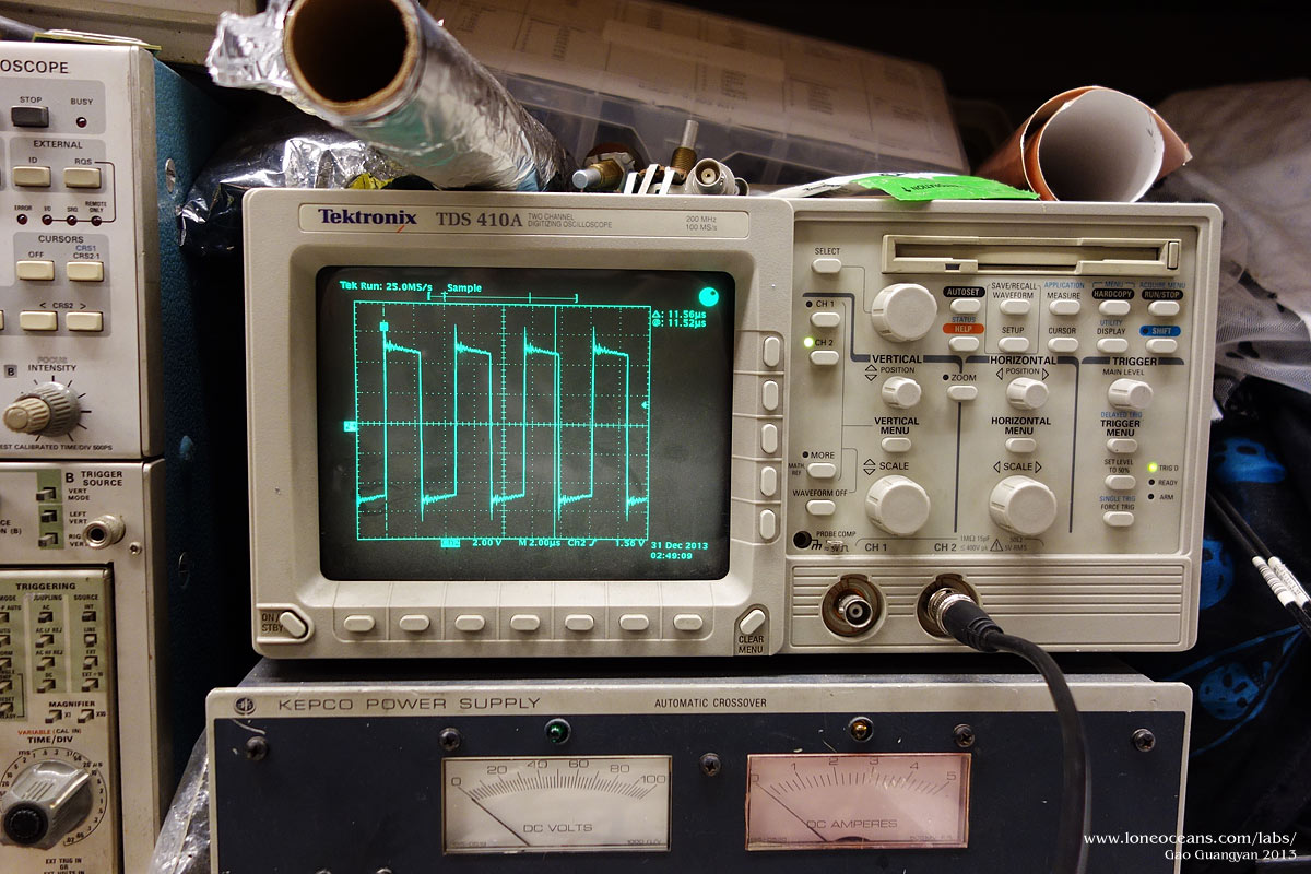
The GDT was wound using the classic
method of using a single CAT5 Ethernet cable (4 twisted pairs)
for a total of ~14 turns on a large ferrite core, each going to
the IGBT with a 1N5819 and 5.1R gate resistor per IGBT. It is
important to select a suitable ferrite core, and this was tested
by wrapping several turns of test wire on it, and checking its
output with a square input from a signal generator at around 60
to 70 kHz. The output should be as square looking as possible
(as can be seen on the right photo with the input being a square
wave). The current transformers were also made, giving a 1023:1
step down ratio. Cores used were the Fair-Rite 5977006401 Type
77 and 5000-1 Fair-Rite cores. Note that I stacked them to
reduce the number of cores.
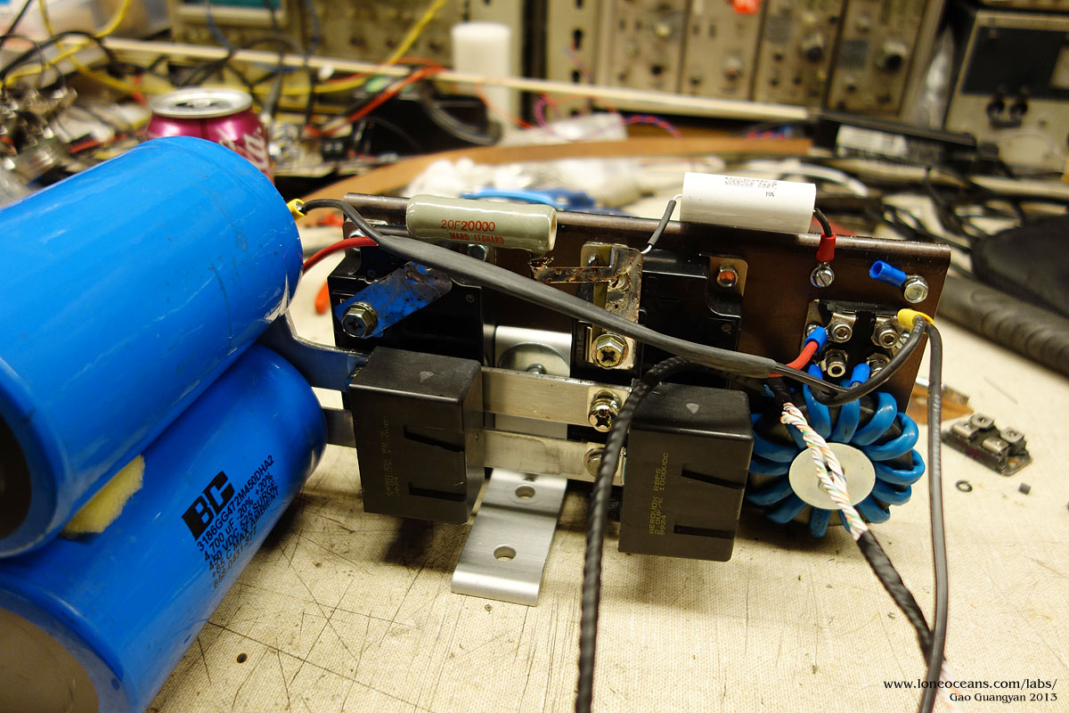
The bridge was then connected to two bus caps each rated 450V
4700uF, forming a doubled circuit with the rectifiers. This puts
the bus capacitance to only 2350uF at 680V (input max), making
it a little small but should work fine (my DRSSTC 2 has worked
really well with a doubler with less than half of this
capacity). Snubber capacitors designed specifically to absorb
transient spikes were also added (4 uF in total). Two additional
features were also added. From the work of Steve Ward, a 7k 20W
resistor was placed across the bridge output. This serves to
bleed any residual charge inside the MMC after each pulse, which
helps start-up oscillations. The reason for putting it across
the bridge instead of the MMC is that we do not need to deal
with the high voltage that builds up across the MMC. Finally, a
small 68nF 3kV film cap was wired to the grounded heat sink and
to the negative rail (note that this is wired incorrectly in the
photo above). This was also invented by Steve Ward, as a
means of protection in case the primary were to be struck by an
arc. This capacitor then provides a path for the arc to ground
and hopefully save the electronics. Additionally, grounds
strikes can cause the 'ground' to bounce up many kV relative to
other supplies (since most grounds are not 0 impedance). This 'RF-bypass'
capacitor helps prevents any large voltage transient that may
stress our silicon switches and their insulation. EMI
suppression is important!
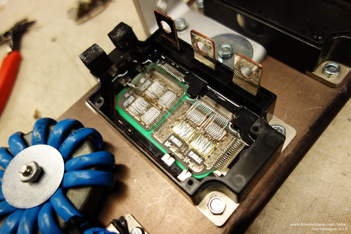
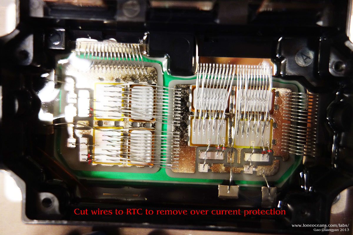
The IGBTs I were using come with RTCs which acts as a
over-current limiter, set at 400A. Disabling it is
straightforward but must be done carefully. The cover was
removed (takes a little bit of fudging and alignment with the
main power leads), then a total of 8 wires were cut, 4 per IGBT.
These wires are crossed in red in the diagram above. Be careful
NOT to cut the gate wires.
Finally, an L bracket was added for easy attachment. The
resulting inverter is very well contained, with 2 power inputs,
2 gate transformer inputs and 2 bridge outputs. All wires were
connected with stranded 4AWG cable, with two 1023:1 current
transformers feeding the feedback and OCD to the driver circuit
as described previously.
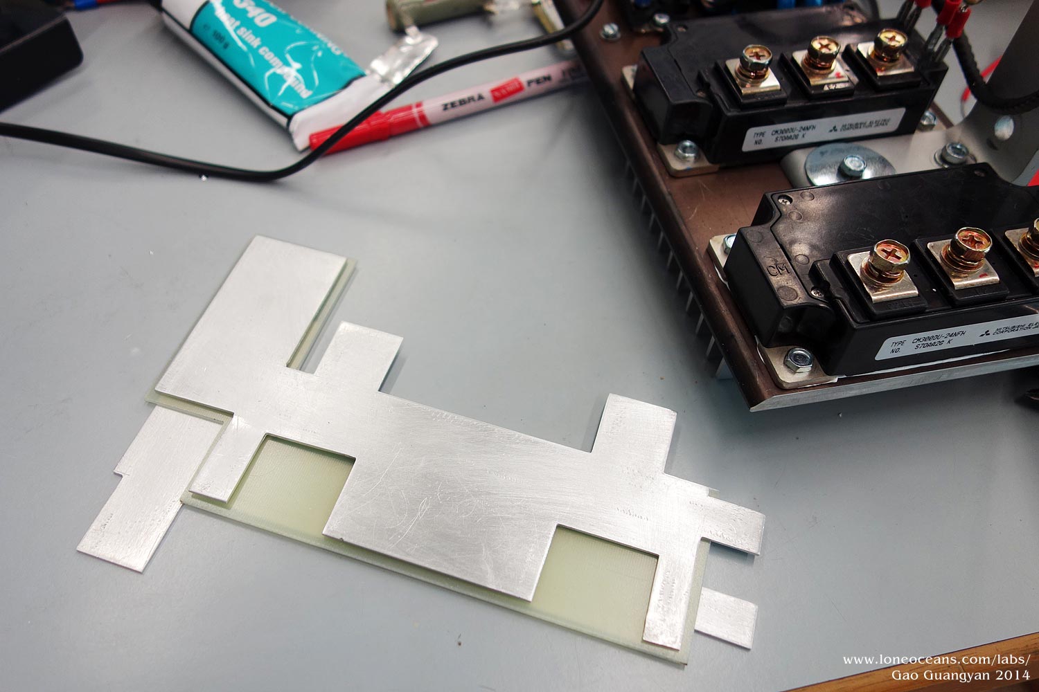
New - an upgraded Laminated Bus
For more reliability in mind and with some extra funding, I
decided to replace the IGBTs with the nice CM300DU-24NFH IGBTs,
good for 60-70kHz soft switching according to the datasheet!
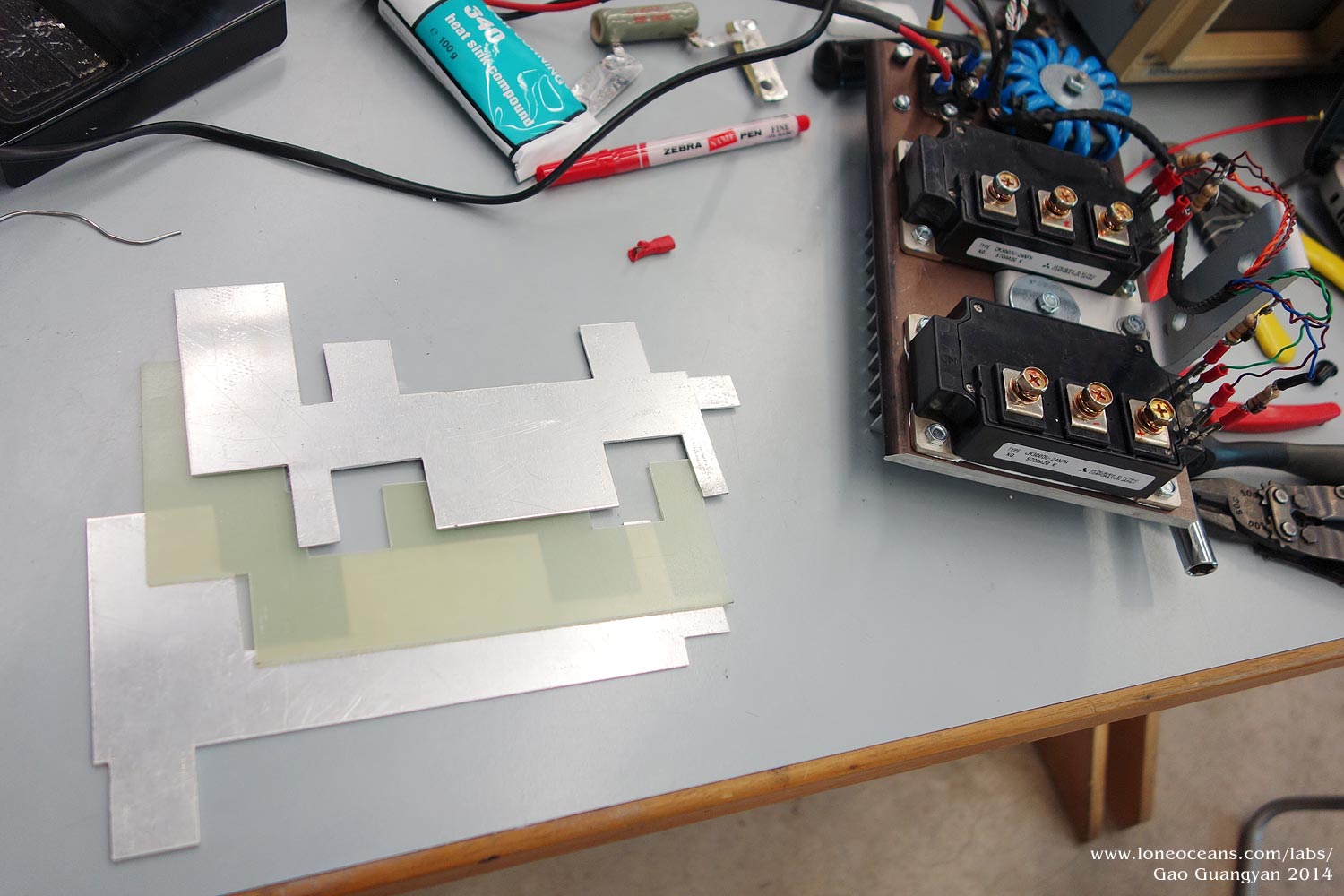
In addition, to make the setup as robust as possible, I decided
to replace the bus with a low-inductance laminated design. The
high coupling between the rails creates a very low inductance
bus which should help reducing switching transients as much as
possible! The laminated bus layout is not as ideal as I would
have wanted it to be, but was designed to fit the existing
physical constraints of the coil.
I designed the three layers and cut them out of FR-4 fiberglass
and aluminum sheets (1/16"). Tabs were included and allow for
easy connection. The bus was glued together and then bolted onto
the bridge.
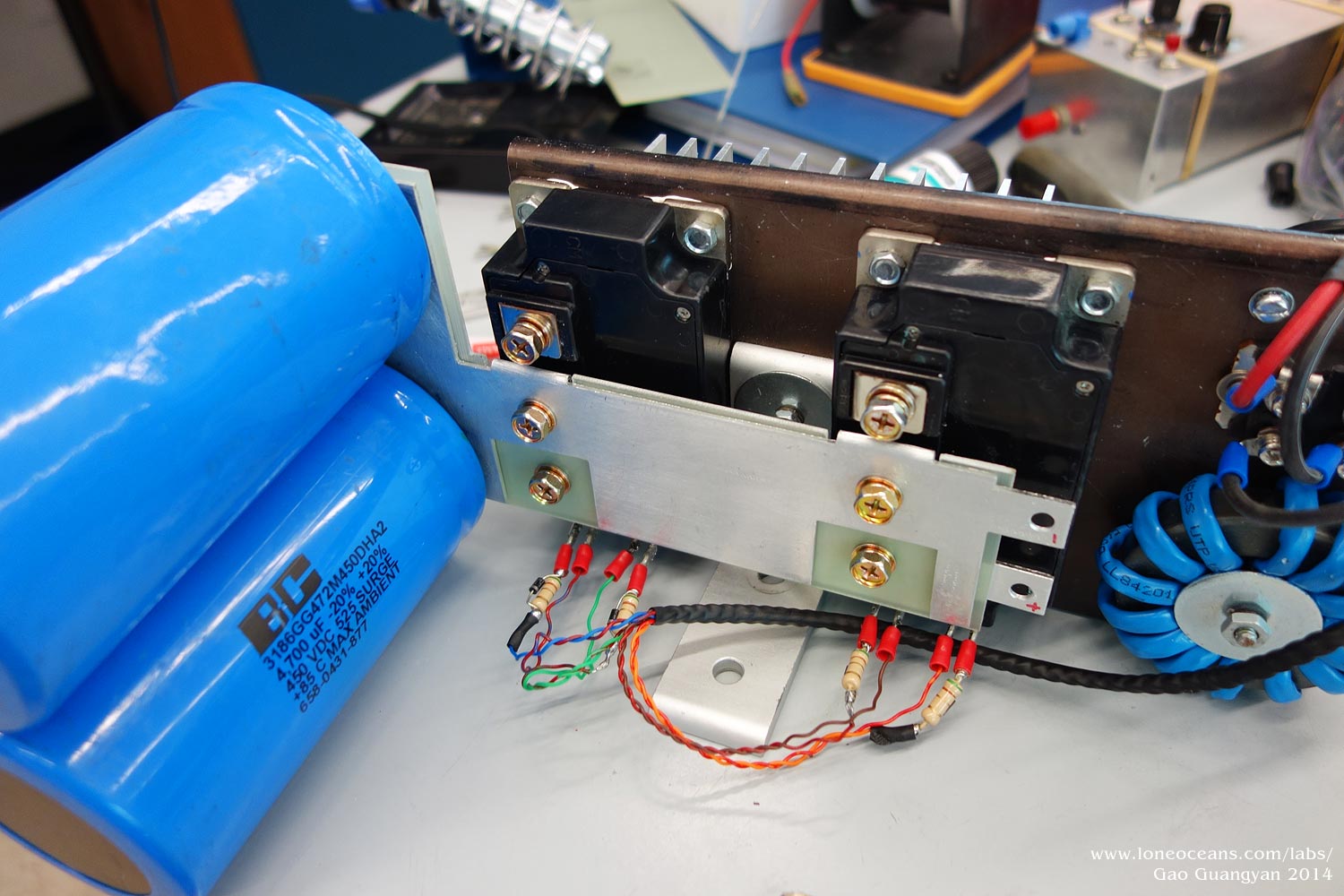
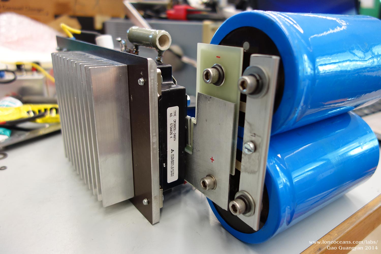
The result turned out to be much nicer than I thought it would
be and I am very pleased with how it came out :). The laminated
fiberglass and aluminum have no problem supporting the big
electrolytic capacitors. Note that the completed bridge block
also includes the GDT, balancing resistor, bleeder resistors, RF
bypass cap as
well as doubler diodes and snubber capacitors.
Resonant Capacitor
I was originally planning to use the famed CDE940/942 series
polypropylene film capacitors, but making a suitably sized one
(I wanted somewhere between 300 and 400nF at about 10kV) was
turning out to cost several hundred dollars. Eventually with a
great suggestion from Bayley, I was able to obtain these nice
set of capacitors from Ebay. These are the Eurofarad SP2550
3.75uF 580Vrms 152Arms film capacitors. These were wired 10 in
series for a 375nF bank good for 152Arms. Check out the 4hv
thread on these capacitors
here.
Enclosure and Box
To put everything together, I first laid out all the components
on the floor and managed to fit all of them within a 18.5"
square. I then machined two 15mm plywood pieces ($10 in total),
one forming the base and the other forming the top where the
primary and secondary coil will sit.
Appropriate holes were cut and drilled into the two wooden
pieces. The layout of the components were adjusted, then each of
the boards was then coated with three layers of
varnish for protection.
Four nice rubber wheels ($12) were then
screwed onto the base for easy transport. The two platforms are
separated by 1" x 9" PVC supports ($1) and held together via M6
threaded rods.
The total volume of the box turns out to be only
63% of that of my Tesla Coil 2 mark ii
(albeit with a larger secondary)! Hopefully, it will produce
even bigger sparks!
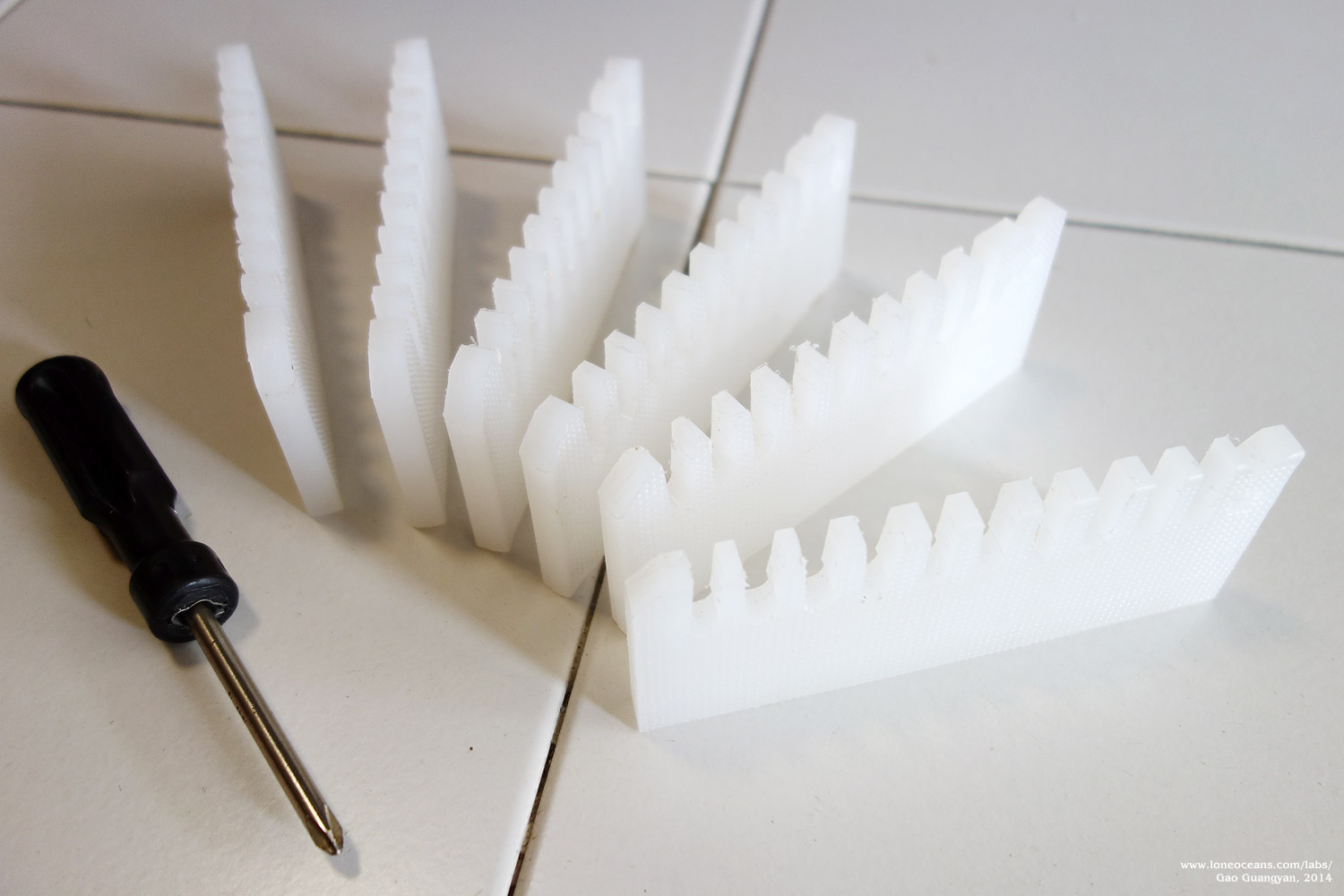
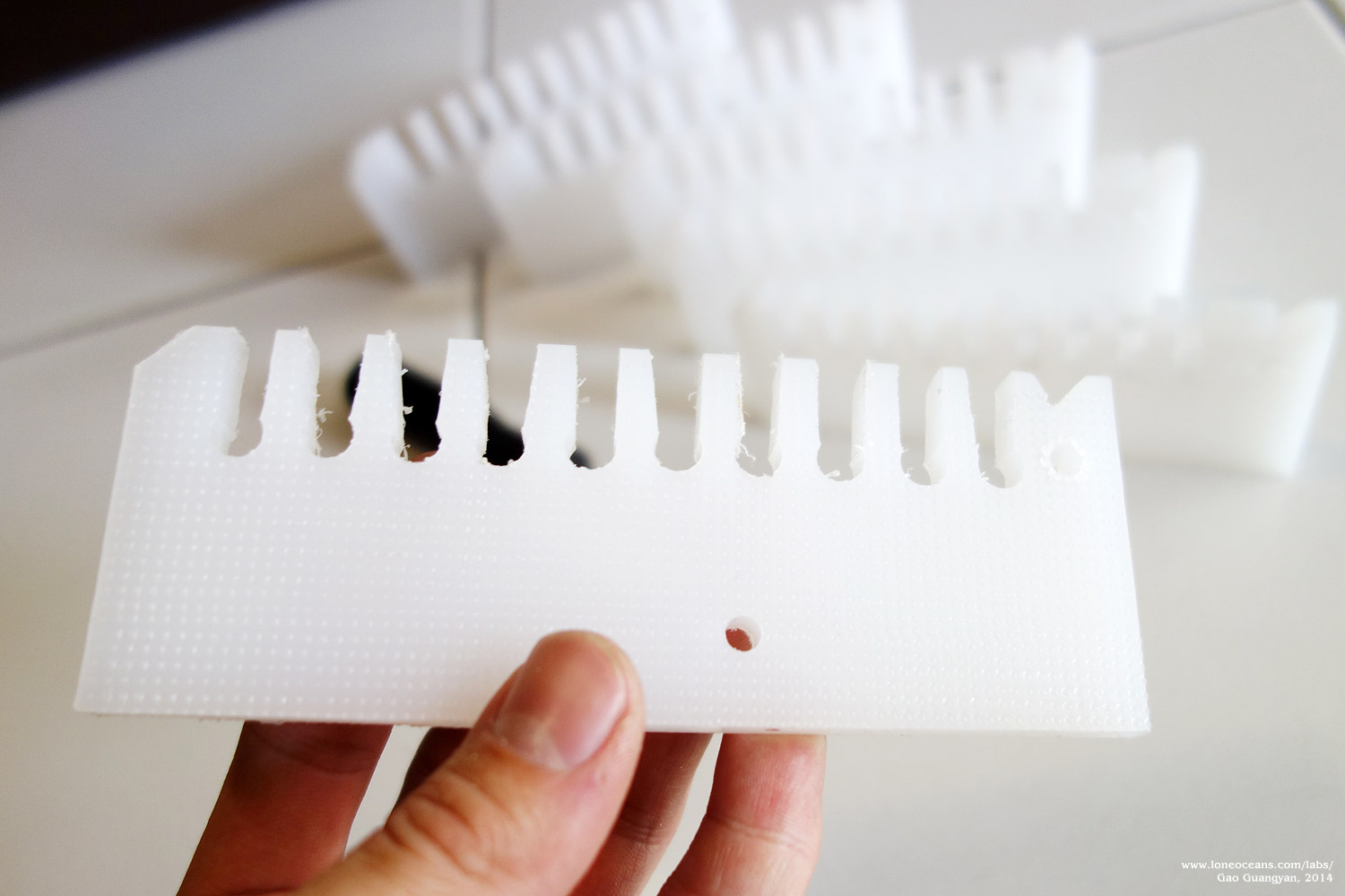
Primary Coil
I decided to use the tried and tested snap-in polyethylene
supports for the primary coil just as I had made it for
Tesla Coil 2 mk ii, using 6 supports
instead of 3. I used a large 10mm spare chopping board as the
base material. The choice of PE was straightforward due to its
ease of machining, low cost (plastic chopping board!), and its
softness made it easy to press-fit the primary coil into the
supports, although admittedly, a more heat-resistant material
would be a better choice.
Without any access to a proper machine shop or a laser cutter, I
cut the materials by hand using a jigsaw and a drill press. The
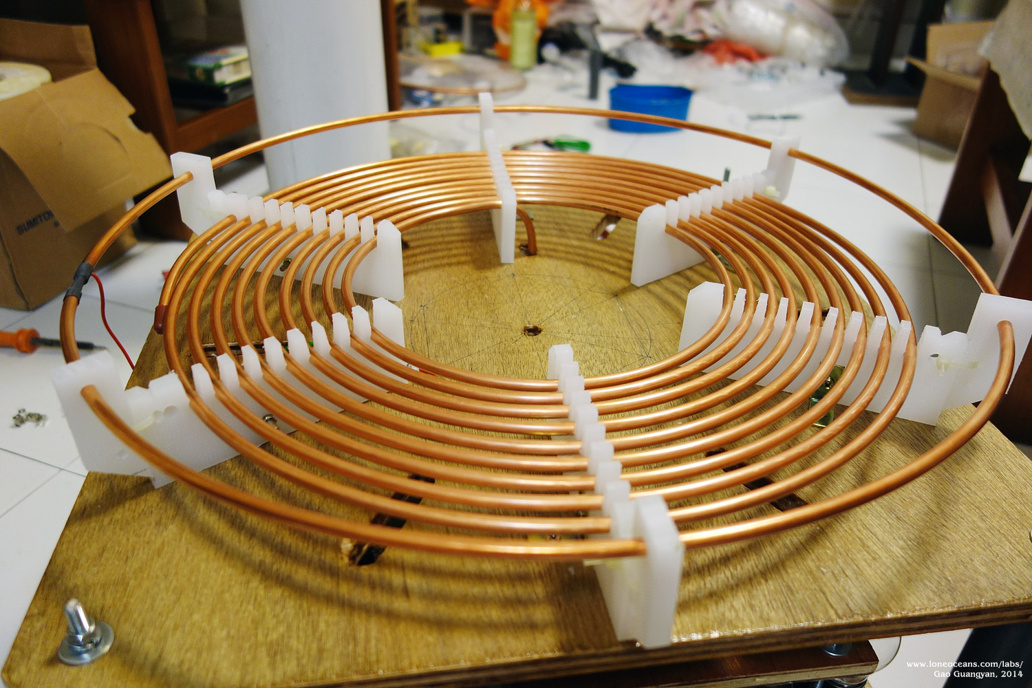
size and spacing of the primary coil (1/4" copper tubing,
costing SG$45 for a 25 ft reel - copper prices are going up!)
was decided to be 12mm, which allowed a total of 9 turns to fit
within the the 18.5" square base. These were then affixed down
to the wooden base via small L brackets.
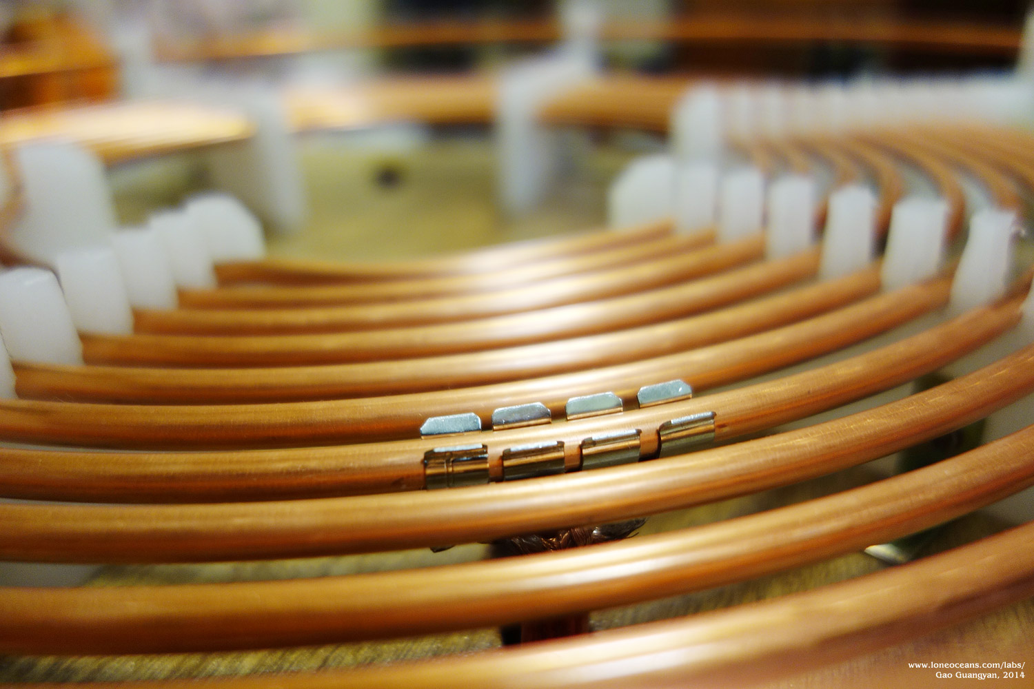
Once done, the 1/4" tubing was press-fitted into place, and the
leftover tubing was used to make a ground strike ring. The
result is a simple, sturdy primary coil.
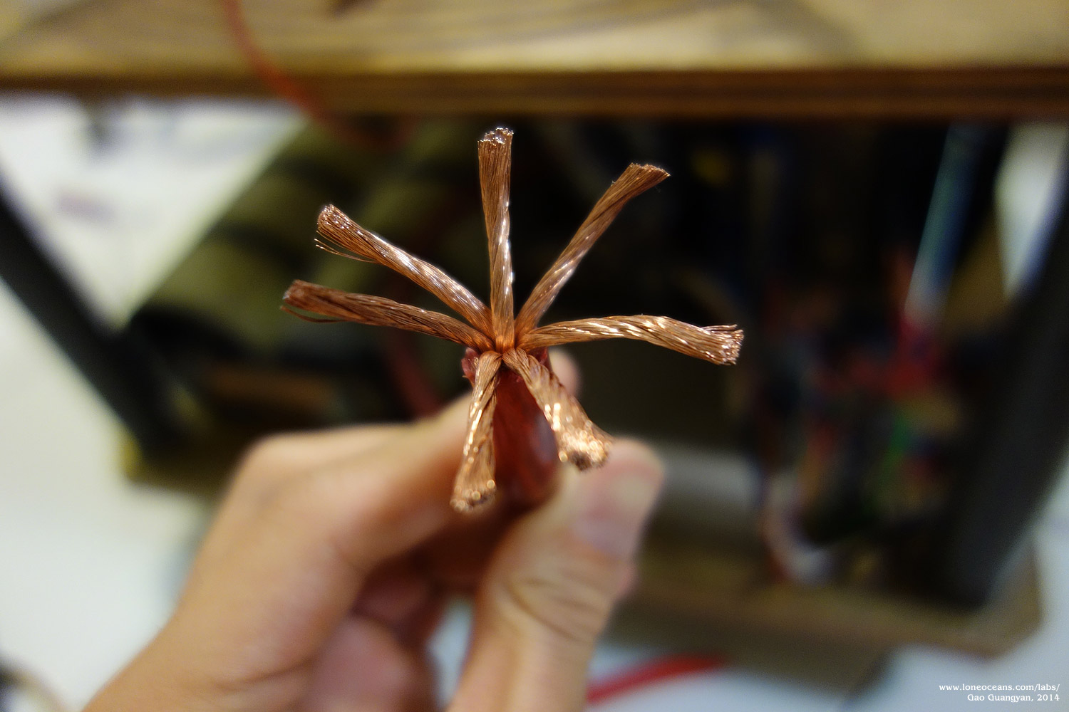
Finally, the primary tap was made from 4 fuse holders soldered
to stranded 4AWG primary cable allowing for a secure and
adjustable connection.
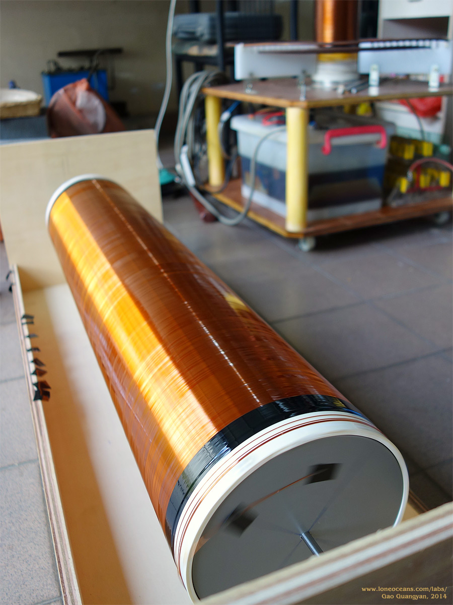
Secondary Coil
Having made many secondary coils now, the construction of this
one was relatively straightforward.
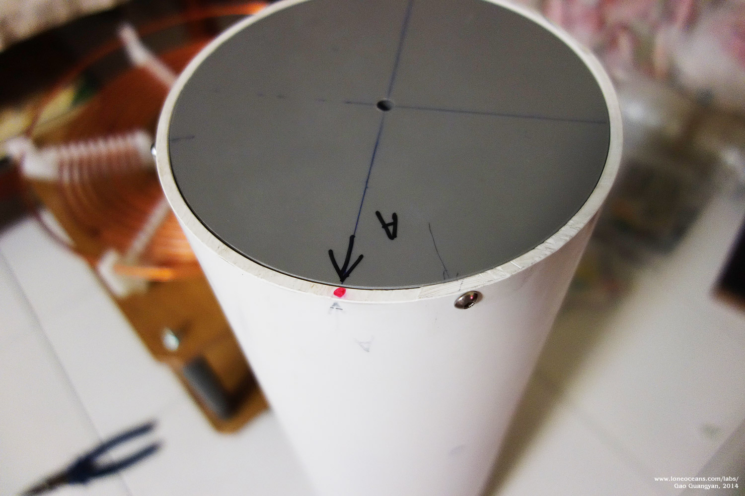
To begin, I used a 6.3" PVC pipe 30" in length and machined two
end discs out of 12mm PVC. This was attached via three screws through the sides of
the PVC pipe into holes tapped into the thickness of the grey
PVC discs. This allowed me to put the pipe onto a makeshift
wooden stand
which I could then wind the wire on.
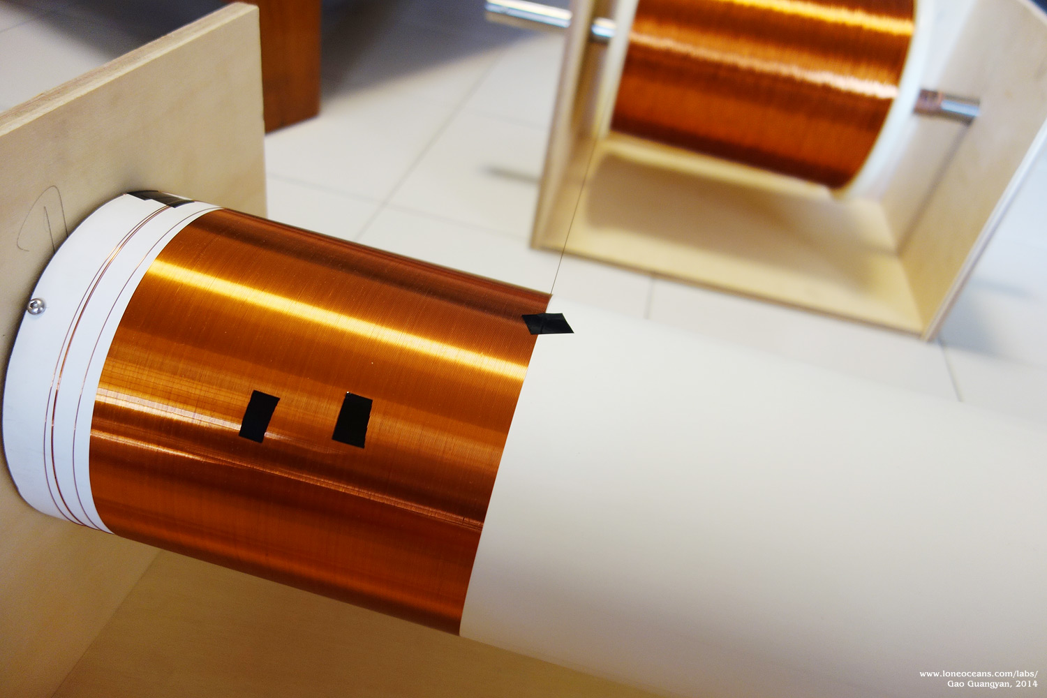
The coil was wound for a total length of 27.5" with 0.35mm (SWG
29) double coated enameled copper wire for a total of just about
1850 turns. The wire reel I was using weighed just about 25kg,
so a sturdy wooden stand was constructed to hold it into place,
allowing it to rotate smoothly on a 1" stainless steel pipe.
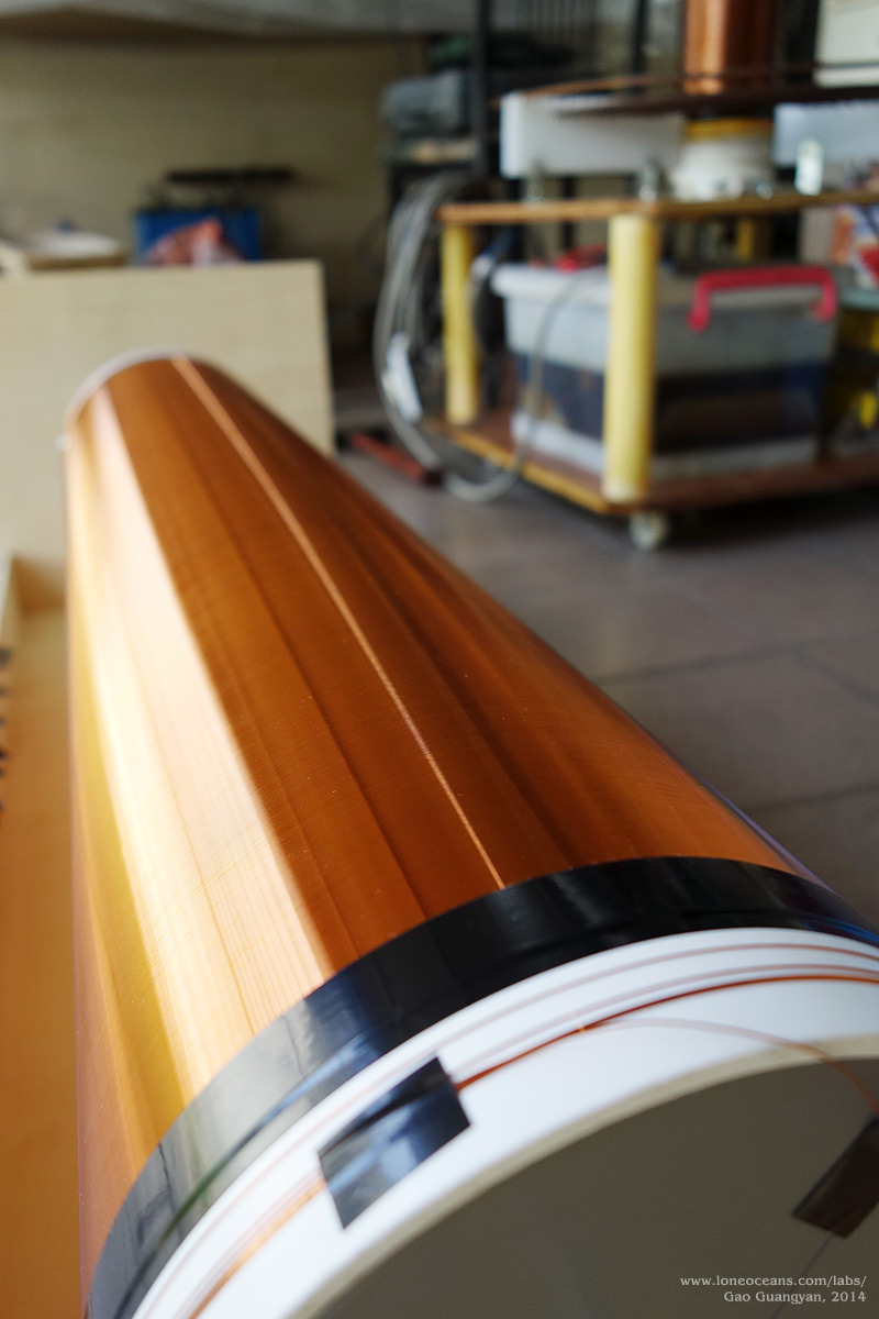
After the coil was wound, the ends were secured with black vinyl
tape. To seal the windings, the coil was then
carefully covered with four thin layers of Polyurethane varnish,
sealing and protecting the coils. To prevent dripping, a drill
connected to a variac was connected to the coil (about 60rpm)
whilst the coil was being varnished.
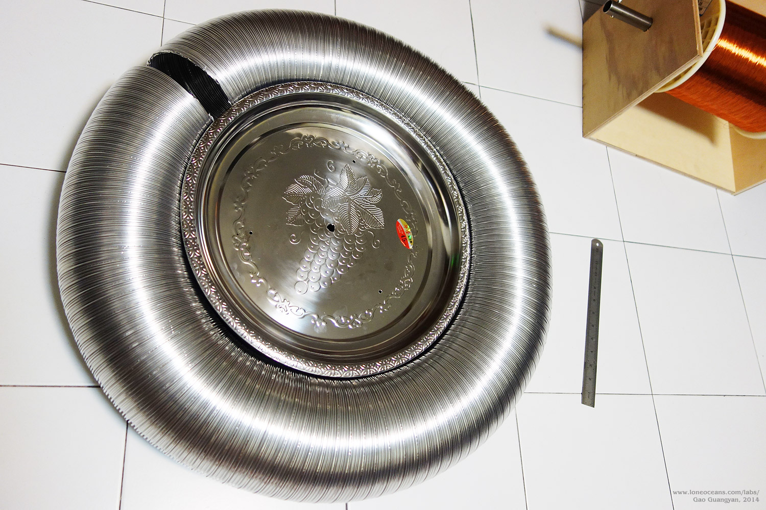
Toroid
A big coil requires a big toroid! DRSSTCs especially like big
toroids!
I originally planned to use a AWG 30 or AWG 29 (or SWG 30) wire
to wind the secondary which would have allowed me to achieve a
sub 80kHz frequency with my existing 5.5 x 20" toroid. However, the
only wire I
was able to get was SWG 29, which required a larger toroid for a
suitable resonant frequency. Thus I decided to simply use 6"
aluminium ducting which was formed into a large ring 30" in
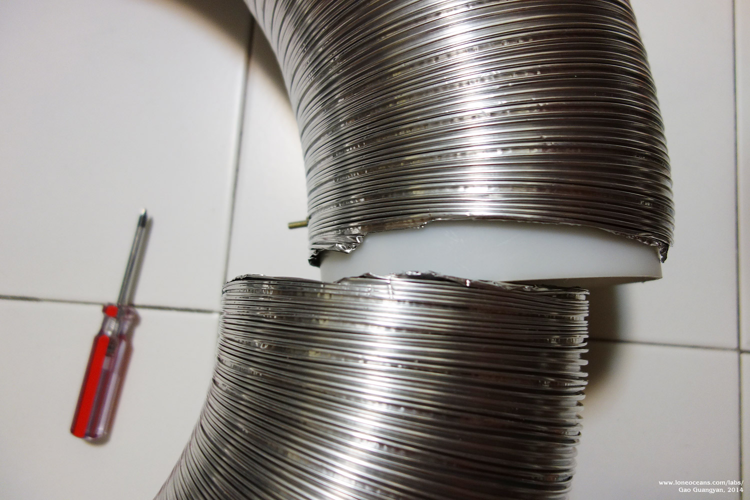
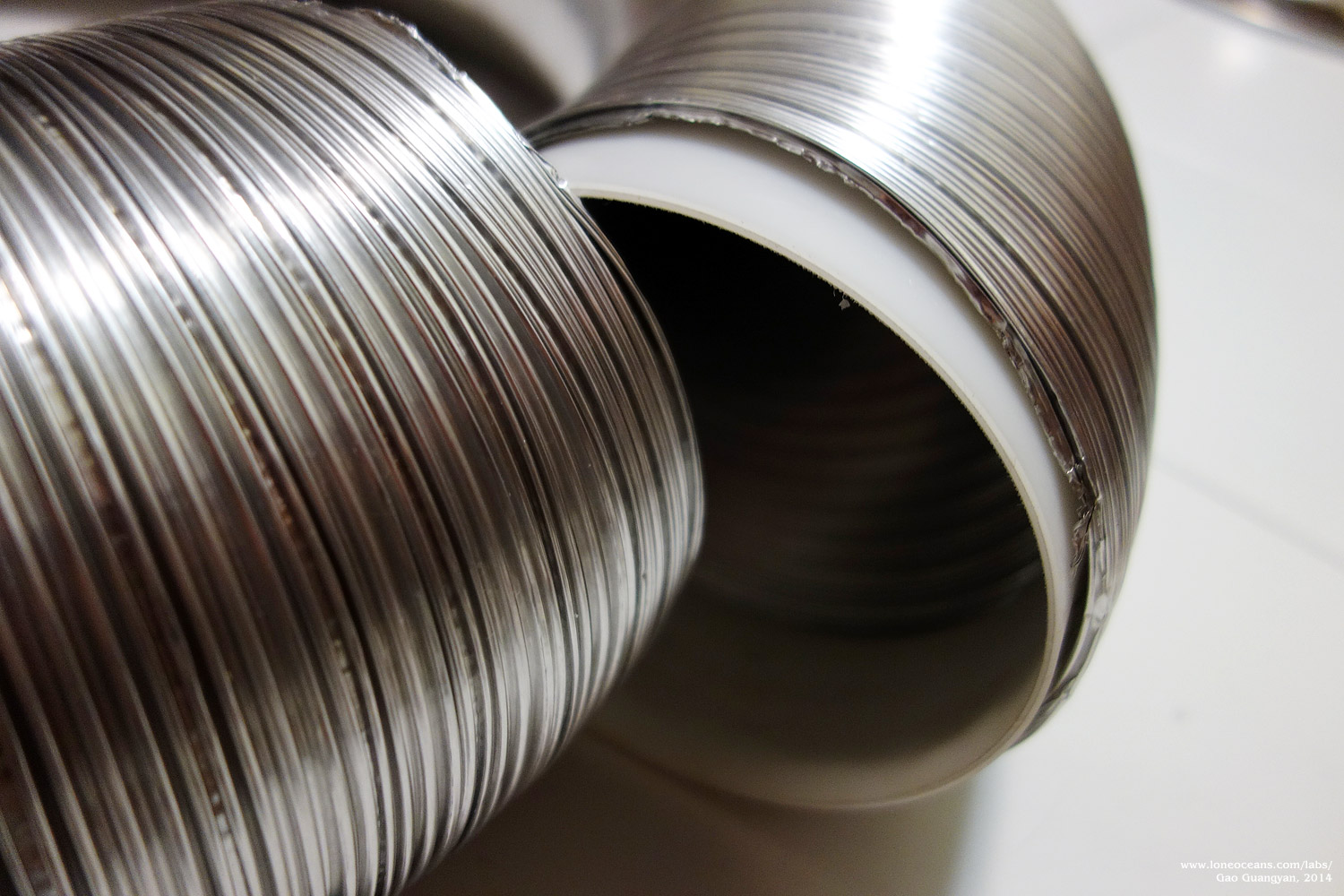
diameter. A
thin plastic collar 2" wide was used to secure the two ends
together.
In the inner side of the toroid, two bolts were used to secure
the plastic band to the ends of the toroid (using some clever
positioning), and the connection was secured using aluminium
tape. Finally, two 45cm stainless steel serving plates were used
to hold the toroid in place and held together with bolts (they
were cheap :) ).
Above is another picture of how the toroid was constructed
inside. PVC spacers were used to hold the plates apart. The
torus sits nicely held together by its own compressive tension.
Feb 2014
At this point with the coil basically complete with only tuning and
testing to go, the project caught the attention of the Singapore
Science Centre!
Leaving the coil in my house would be nice, but I decided that
it would serve a far greater purpose with the Science Centre
instead of collecting dust in the corner of my room. So we worked out a collaborative plan to bring a
new prototype exhibit to the Science Centre via this coil!
The Singapore Science Centre
(SSC) has had a conventional rotary spark gap coil on exhibit (and with
daily shows) for the past several years. While it has been a
very successful exhibit, it is perhaps time to usher in the new
breed of musical electronic coils. With this project, I hope I
can bring some of this new technology to the show and to
revitalize the tesla coil exhibit!
The completed coil all assembled up in the prototype
workshop.
With this collaboration, I was able to obtain some workshop
space to conduct some testing and tuning for the tesla coil. In February
2014, the coil was moved to the prototype
workshop of the SSC for final touch-ups and tuning.
Preliminary Measurements and Testing (Feb 2014)
With all the main physical parts of the coil complete, it was
time to do some preliminary measurements on the resonant
frequency of the circuits. The current specifications are as
follows with the secondary coil 6.3" x 27.5" with ~1850 turns of
0.35mm wire. The primary coil varies with turn 5.92 at radius
7.1" and turn 5 at radius 6.62". The main toroid measures 28.5" x 6"
with a secondary one being 12.6" x 2" for corona control, spaced
about 7 inches apart. Simulations were done using JavaTC 13.
Primary Coil
Turn 5.92 gave a measured resonant frequency (with no secondary
in place) of 64kHz, close to the simulated 67kHz.
Turn 5 gave a measured resonant frequency of 78.9kHz
(with secondary and toroids in place) with a simulated 77.95kHz.
Turn 5.41 gave a measured resonant frequency of 71.8kHz
(simulated 71.88kHz)
(25.6uH, 417nF).
An extra turn of ~6.41 should give 61.46kHz (simulated).
Secondary Coil
The standing secondary coil with no toroid gave 143.3kHz
which suggests 1850 turns of wire - considering optimal packing
would be 1887 turns (with wire thickness with enamel of 0.37mm),
this seems to be a good figure of 98% packing.
With both toroid and secondary in the middle of the primary
coil, a secondary resonant frequency of
79.9kHz was measured, close to the 78.4kHz predicted.
With simulated streamer loading of 2m wire from the top of the
toroid, the new resonant frequency of 70.5kHz was
measured. With a coupling of 0.148k, this places the
lower pole of the circuit to be 74.5kHz.
This suggests that turn 5.41 on the primary coil should yield
good results which is what the primary coil is currently set at,
with a 11% detuning. Hopefully, this will give big sparks for
the goal of 2m!
From this, one cycle will take 14ns. My interrupter is set to
135ns max at the moment, which should give 9-10 cycles of run
time. The coil was later found to run very well with just 5 RF
cycles.
With the resonant frequencies checked, I proceeded to test the
logic and bus with an isolated power supply. The driver was
tested by applying a small 70kHz sine wave into the feedback
input, and measuring the drive output. A few debugs later and a
replacement of a dead resistor and all checked out as expected.
Various scope shots of the primary current and inverter
output shown after phase lead tuning for ZVS and minimized
ringing at about 78.9kHz
This was then connected to the inverter and the bus charged up
to 50V. It is important to test the inverter with an isolated
supply, which helps in measuring bridge output (especially since
I'm using a voltage doubler. Current limiting on the power
supply also helps. In this case, the bridge was found to be
working as expected (very important not to mix up the phase of
the gates which will lead to shoot through) and started up
reliably by itself with 50V on the bridge. Finally, phase lead
was carefully adjusted to make ringing to a minimum (checks out
ok but would prefer an analog scope to find nanosecond
transients) and is now ready for power testing!
First Testing and First Light
First testing was carried out on 6th Feb with an isolated power
supply at 60VDC into the bus limited at 3A. The pulse width was
set for a maximum of 50us+ (3 to 4 RF cycles). The coil
responded well, producing a clean buzzing sound you'd expect
from a tesla coil, and produced it's first 2-3" spark
to ground
at low power! This started interfering with some other
electronic equipment including the power supply (all was fine)
as well as the telephones in the workshop(!),
so next up will be power testing from a large variac in a
suitable space.
Additionally, I was thinking about the sort of currents I would
expect during power runs. To
determine the current, we can use the maximum voltage in the MMC across the impedance of the primary. The primary current can
be determined as follows:
I_p = V_mmc / (R_pri + 2 * Pi * f * L_pri)
We can also determine the upper bound of the MMC voltage.
Suppose the bus is charged to V. On a full bridge, we switch
between -V and +V. On the first half cycle, the MMC is charged
to V. On the second half cycle, it becomes -2V, then 3V and so
on. So a rough idea of the MMC voltage can be given by V_mmc = V
* N, where N is the number of half cycles. For a previous test
running off a power supply, I measured 59A peak in about
3.5RF cycles at 57V on the bus. The calculated current comes up
to be 62A which seem to be in the ballpark (78.9kHz).
At 71.8kHz (current configuration after power testing), at
200VAC in, I will hit 793A just after 56us (4 cycles). At 150VAC
in, I will hit 743A at 70us (5 cycles). At 135us, this gives me
764A with 80VAC input! In the maximum case of 135us and 240VAC,
a max current of 2294A is achieved, or 1912A at 200VAC, 1433A at
150VAC. Note that this is an approximation of the highest
possible current with no losses in the circuit. In practice,
energy is transferred to the secondary dropping it
significantly. In addition, spark loading drops the quality
factor Q of the circuit - resulting in a higher rate of energy
loss.
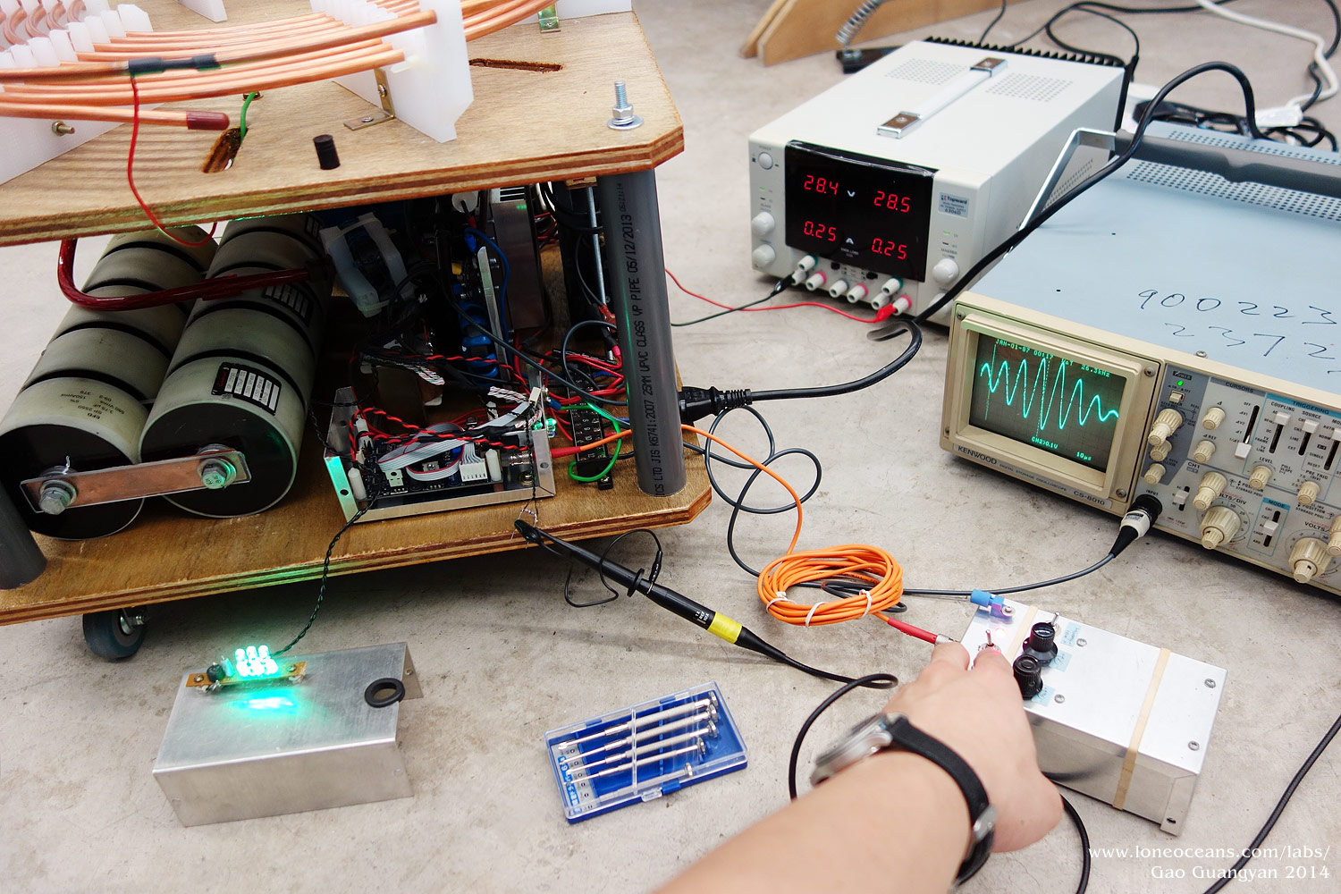
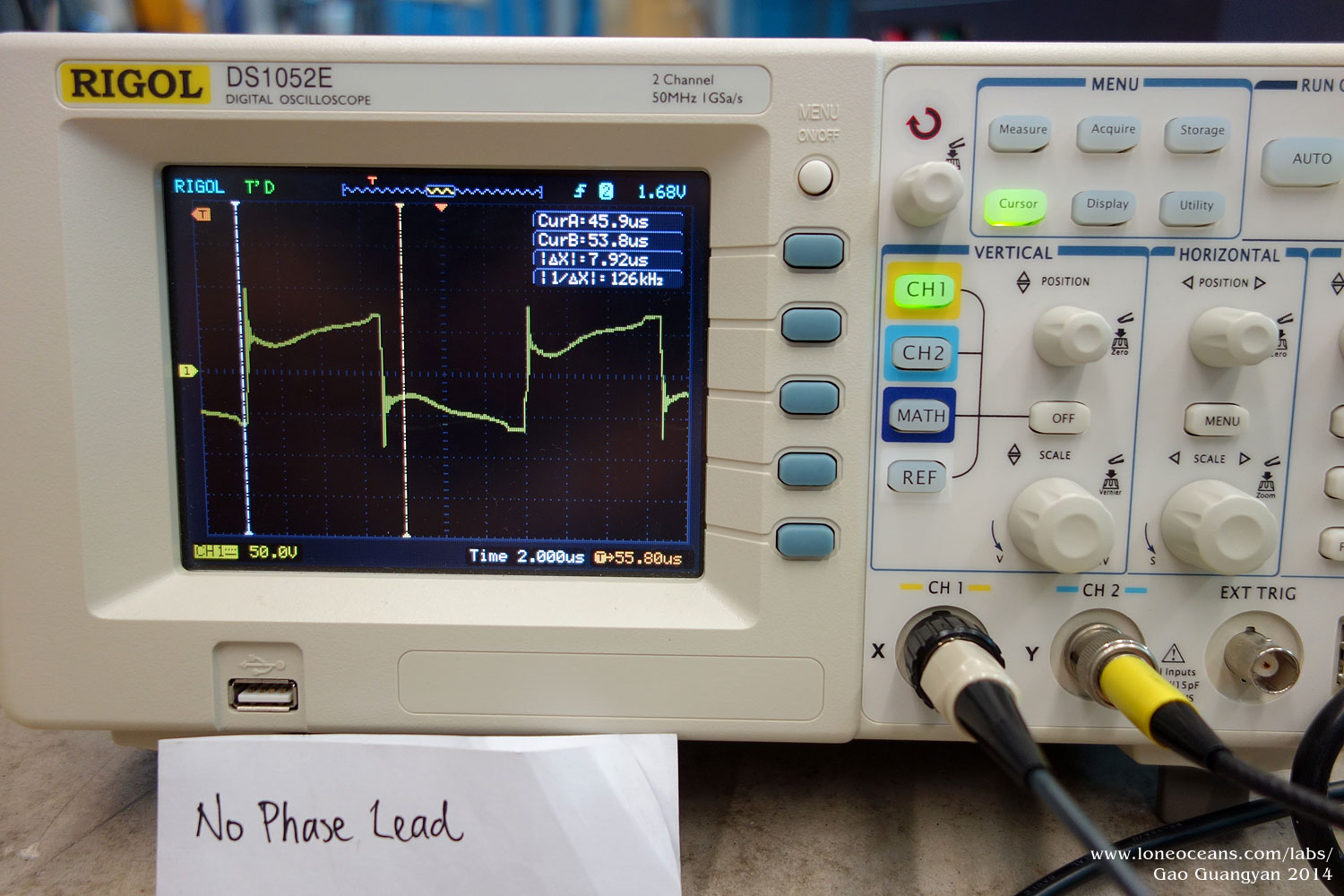
Phase Lead - Additional Tuning with a real scope!
I was originally using a 40Ms/s scope to check the output of my
bridge, but this was not very useful - the low sampling rate
meant that I could not see if there were any voltage spikes or
not on the bridge! So I borrowed a 1Gs/s Rigol scope! This was
very useful. I've including some scope shots and hope this will
be helpful to anyone out there debugging their DRSSTC!
For those who are not sure what phase lead is, phase lead is a
method of switching the transistors in the inverter slightly
earlier than zero current crossing. This is beneficial due to
the short delay the transistors take in becoming fully
conductive. Switching early allows us to switch precisely when
the current is at zero by using a reference current that leads
the actual primary current! An adjustable inductor is used to
adjust how early the switching begins. This has strategy has
been implemented in several control schemes, notably Finn
Hammer's Prediktor and Steve Ward's UD2.
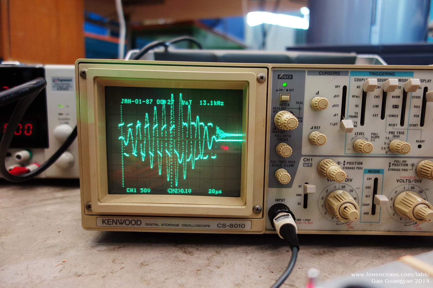
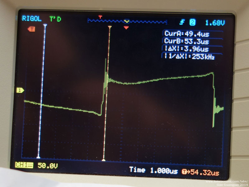
The trace above shows the bridge output. Look what happens when
I adjust phase lead. The lead increases from left to right.
Essentially, phase lead allows me to adjust how early I am. The
left shows no phase lease - switching is spiky at the
transitions, and the bridge rings. As phase lead is increased,
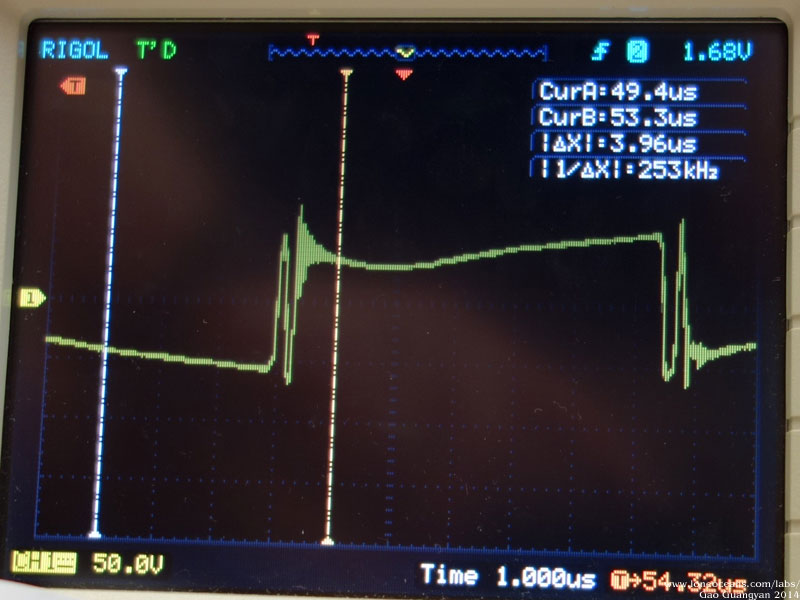
the spikes are reduced. However, something interesting is
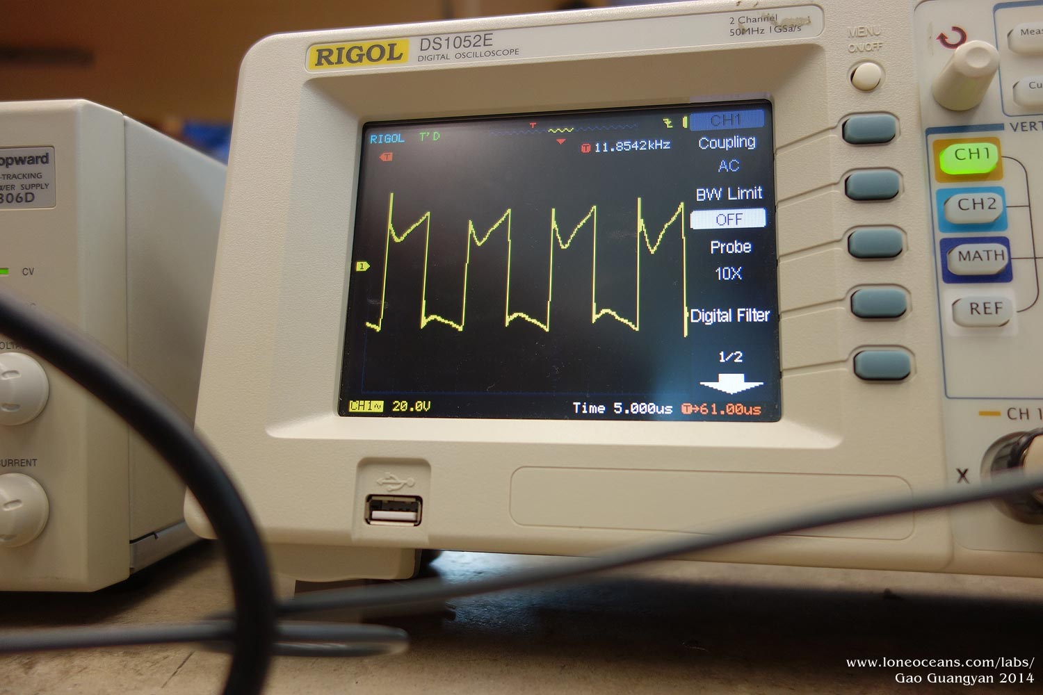
happening here. Take a look at image 2 (closer up in image 3).
Here, we can see one diagonal leg of the IGBT bridge turning
off. At this point, the primary current causes the voltage to
change polarity as it charges up the junctions of the opposing
freewheel diode. But it turns out that the other leg of the
bridge is taking too long to turn on! The primary current
changes direction (crosses 0) and so the voltage jumps back.
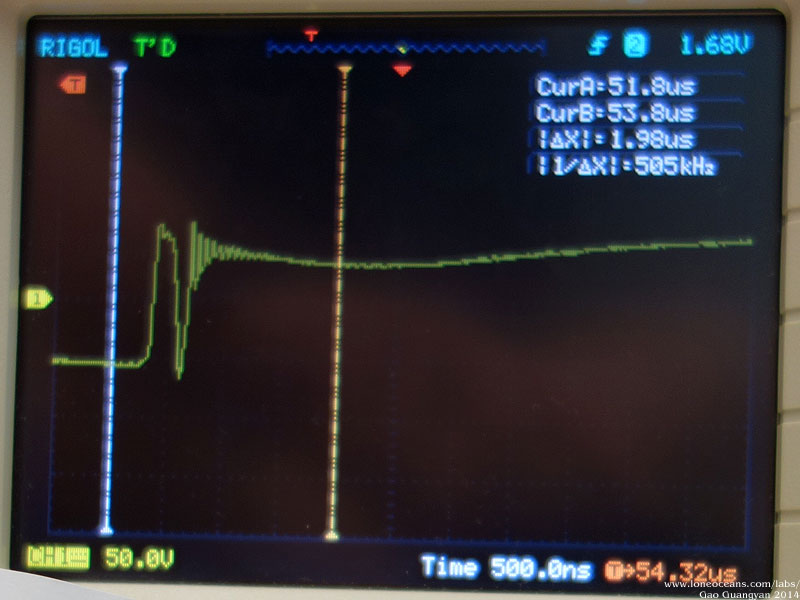
After a while, the IGBTs finally turn on, causing the voltage to
change rapidly. This is very visible in 3, where both the little
spike is observed and the resulting ringyness of the bridge.
When phase lead is advanced even more (image 4), this effect
disappears, but since switching is happening too early,
significant current is switched and spikes are observed. The
conclusion - my IGBTs are turning on too slowly. We can fix this
by reducing the gate resistance.
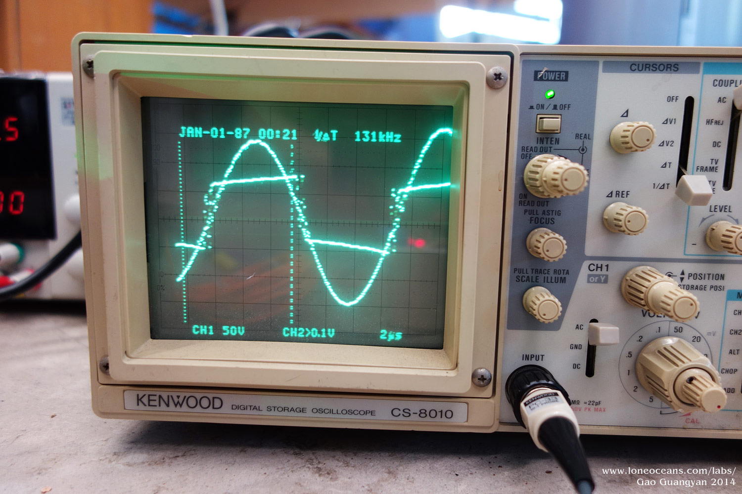
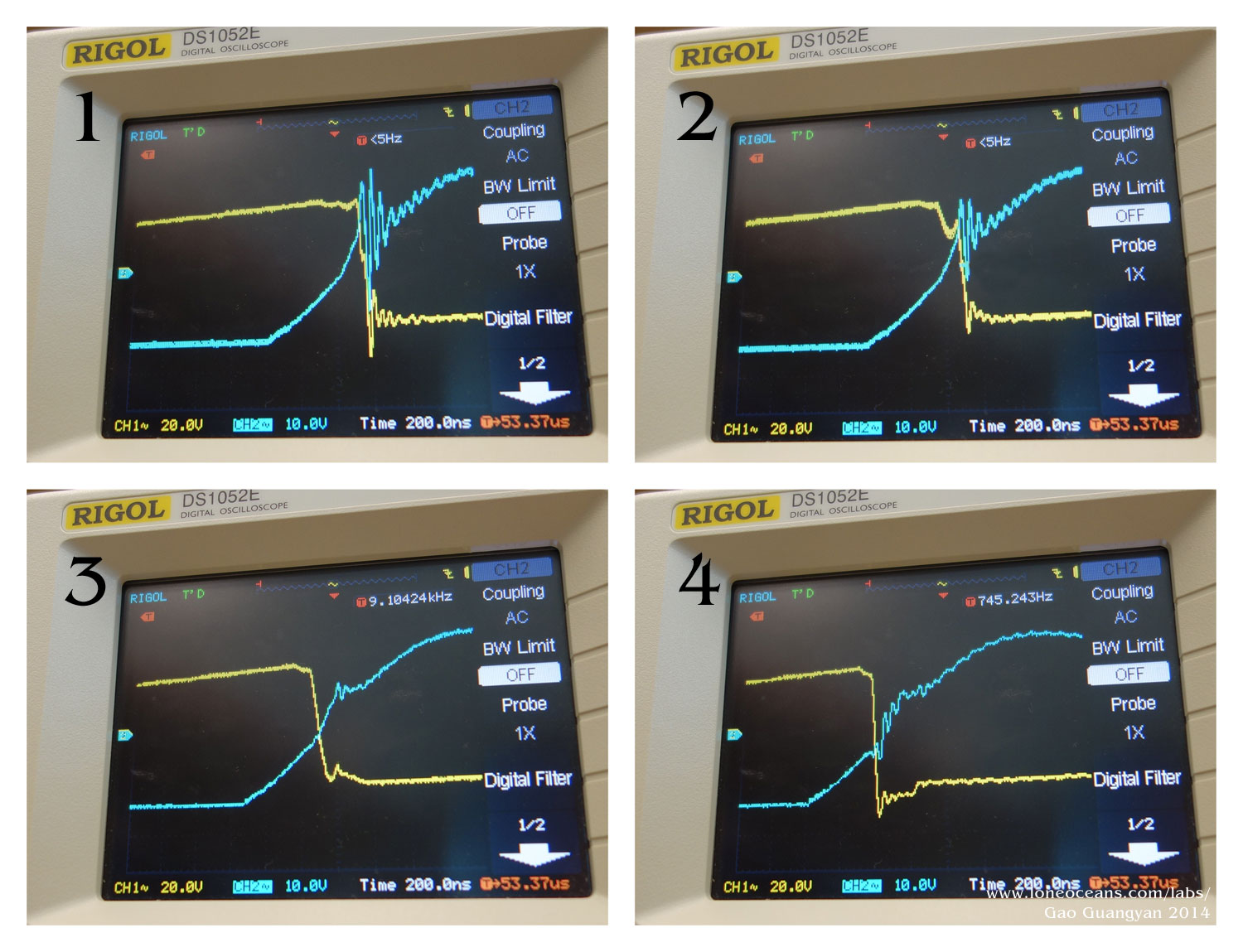
The above 4 images show what happens in an ideal situation.
Here, I've fixed the gate resistance. The blue trace shows the
gate voltage and the yellow, the bus voltage. Image 1 shows no
phase lead. We can see the ringing on the bus. As we advance the
phase lead, we pass through 2, 3, and finally 4 (note the same
result as previously!). Image 3 is the critical point I've set
the coil. We can see a few things at once here.
Note that the IGBT full turns on just when the gate is around
10V. This is very clear in image 3, where the gate voltage rises
from 0 to about 10V, stays there for a while, before going up to
24V or so. At the 10V plateau, this is where the IGBT really
transits into a conductive state. Note that in image 3, just
when the bridge voltage falls to 0, we very quickly fall into
the conductive region. We have achieved zero voltage switching!
This is very desirable and is how most inductive switching is
done. This also produces a very clean ring-free bridge output!
Thus the coil was tuned this way. At this point, I'd like to say
thanks for Steve Ward for a lot of this tuning advice and help
in figuring all this out.
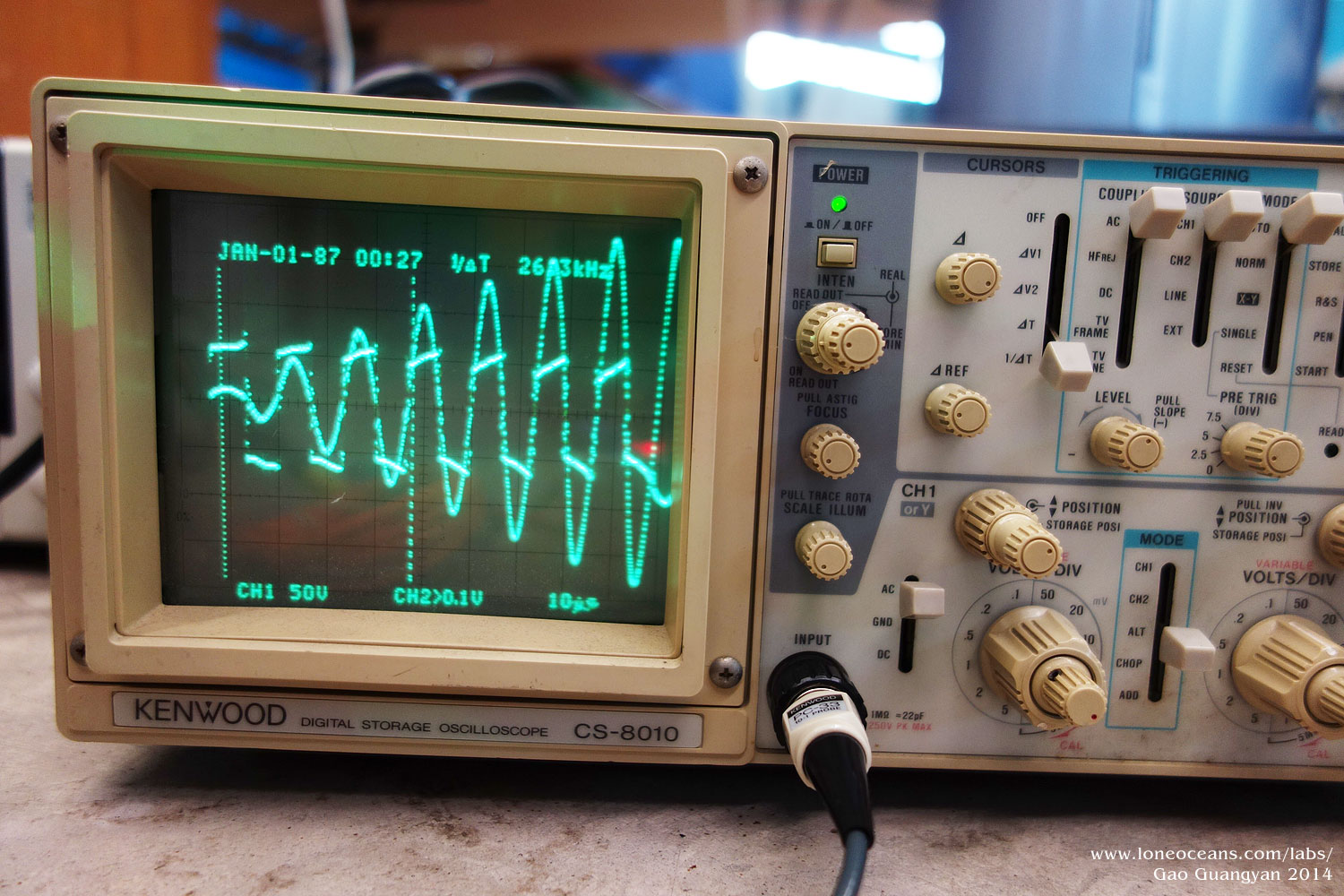
The before and after shots are significant and the bridge no
longer shows any appreciable spikes or ringing! Finally, note
the 'tick' shape on the output of the bridge. The sag is simply
caused by ohm's law while the primary current is flowing. It is
slightly off-set due to the bus inductance. I've set the phase
lead to work the best at about 20% Ipk, and for the later
switches in the entire cycle. This seems to work well in
practice.
Results - Images and Videos
Jan - Feb 2014
Below documents the Tesla Coil in action! Please contact me (see
bottom of page) if you are interested in using any of the
images.
Power Testing - 1
With the coil working as expected so far, it is time to put the
coil to the test. A
large variac (looked at at least 4kVA) was used as the main
power source, protected by a 40A breaker, as well as 15A fuses
on the tesla coil side. The test was carried out at small pulse
widths (all below 110us pulse widths) with input voltages from
50V to 150V in 50VAC increments.
Low power testing at 150VAC
input limited by OCD (~680A), tapped at turn 5.41.
The right photo shows 425VDC on the bus at 110us, achieving
about 6 feet arcs.
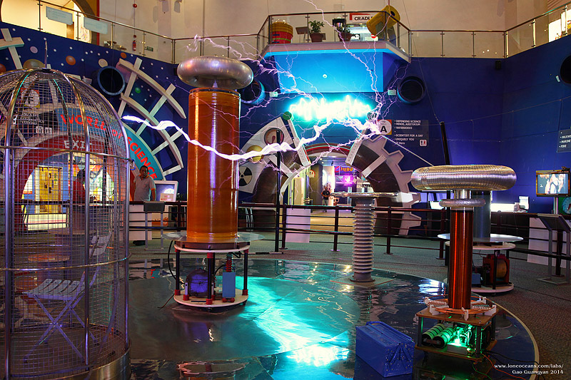
Since the coil was at the Science Centre, safety is an important concern. Fortunately,
the SSC already has a shielded cage at the main atrium which
houses the current conventional Tesla Coil. No more testing at
home! With some help form
the staff, I was able to bring the coil to the main atrium to
conduct power testing in the cage. Needless to say, this was quite
exciting no doubt due to the many curious visitors checking out
the project :).
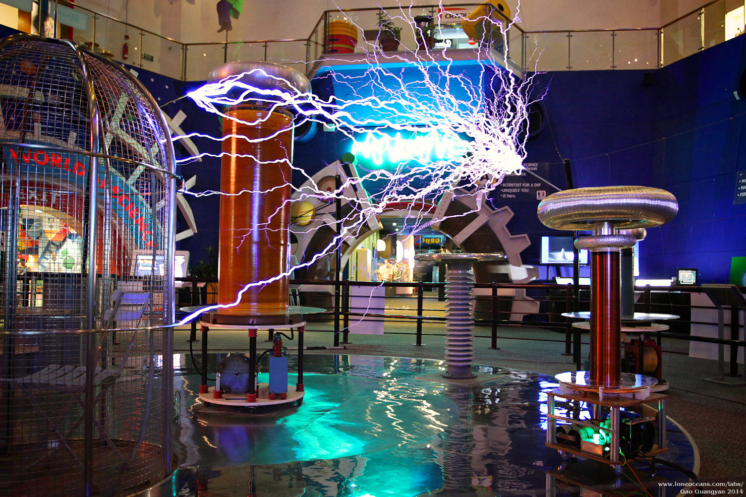
Much to my relief, the coil performed spectacularly producing
sparks and streamers 1.5m to ground easily, with merely 150VAC
to the bus (420VDC out of 680VDC max). I will continue power
testing to a maximum of 240VAC in to assess performance, before
scaling the power back down for reliable operation.
Power Testing - 2
Two days later, I tested the coil at higher power, with the same 150VAC
input (425VDC) at 100 -135us pulse widths. Maximum spark length
today was just about70 inches (1.78m) with occasional
680A OCD trips at about 110us mark and continual trips at 135us.
The total power draw was just around 15A (2250VA) at low (sub
300) bps. However, playing music with high bps promptly blew my
15A fuses, so these will need to be upgraded to at least 30A
fuses. I suspect that the total power draw required to achieve
the same length sparks will actually decrease with increased
tank voltage.
So for more durable operation, several parts were upgraded mostly
in terms of power connections. The IEC jack was replaced with a
dedicated 50A terminal block for easy connection to the existing
power cable, fuse now upgraded using a 30A 3AB fuse, and grounding wiring
adjusted. A ferrite bead was added to the GDT outputs to reduce
common mode noise and the breakout point shortened to a more
reasonable length.
With the new parts, the coil was once again brought out for a
power test, this time operating all the way up to 220VAC input.
Maximum spark today was just in the neighborhood of 1.9m (just
about 6.5 feet), achievable with the current OCD setting
(~680A). Tuning of the primary coil was done with best results
around 5+ to 5.5 with a dropoff at 6 or 4.5.
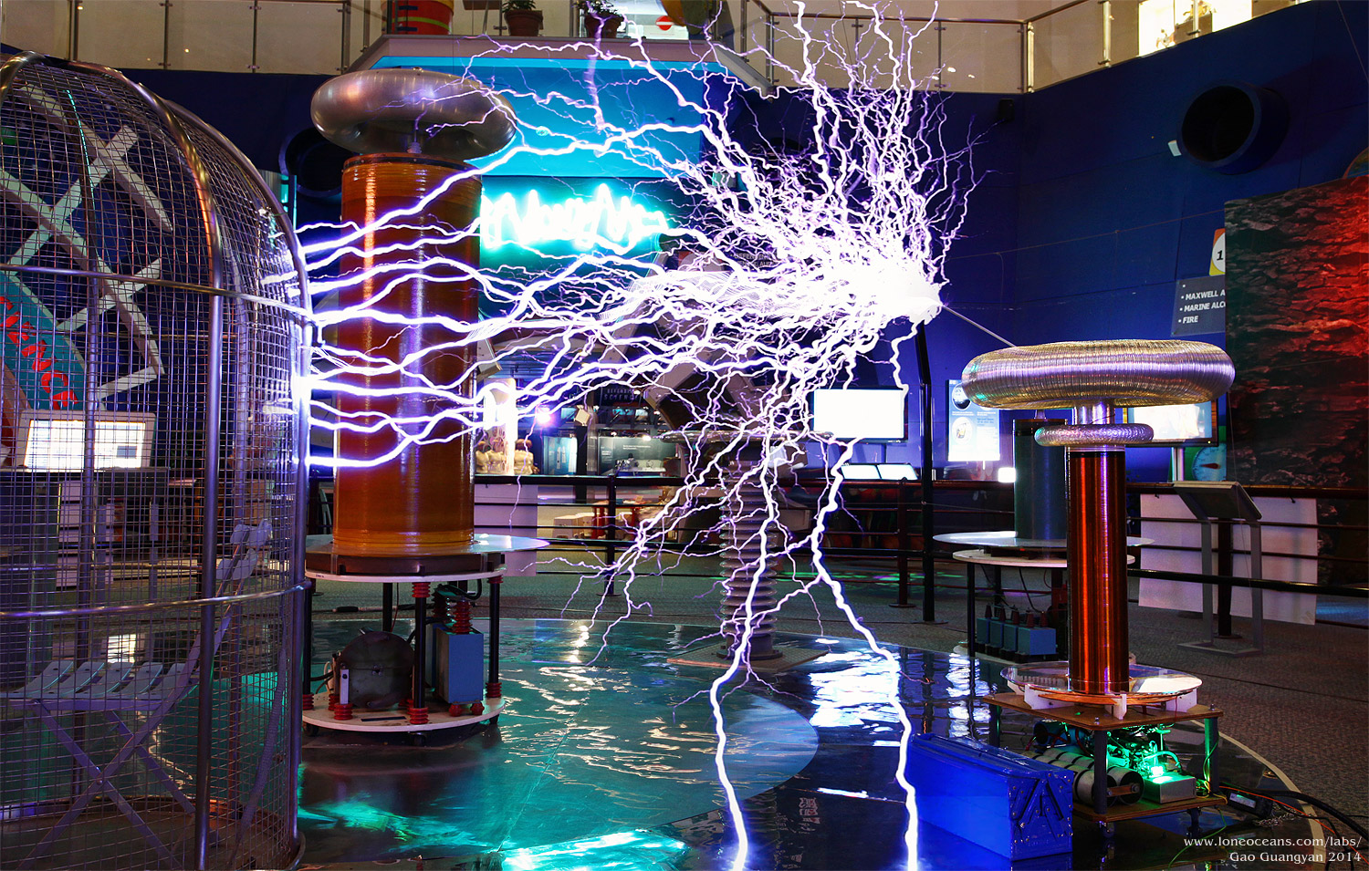
A note about the following images - the Atrium turned out to be
quite bright (e.g. aqua neon sign in the background, light from
second level etc), even with the main lights switched off, and I
was unable to get clear spark photos. Hence most of the photos
below are video frame composites which were assembled using
still images and high sensitivity video capture. They are
however quite representative of how the coil looks like in real
life - the sparks *are* very bright especially ground arcs.
Composite stills from a video with the coil running at 185VAC
on the bus at around 70us pulse widths (5 RF cycles). ~4.5kVA.
6'+ sparks.
At bps of around 200 - 250, current draw was hovering at around
12A with 200VAC in at around 70us. Once the coil checked out
good, I plugged it into polyphonic midi for a 1min continuous
run playing Pirates of the Caribbean. This drew an average of
20+ to 25A, peaking at 30A+ with 185VAC in or so, also at around
70us. Overall performance was great though I have the nagging
feeling that the tuning can be more finely adjusted and the OCD
raised up to 800 or 850A.
For more reliable
running, the coil will probably be turned down to its current
setting after a higher power test! After the full minute run,
the temperature of the primary cables, heatsink/IGBTs and main
power cables were only slightly warm, at most 10C above ambient,
so it should hold up well!
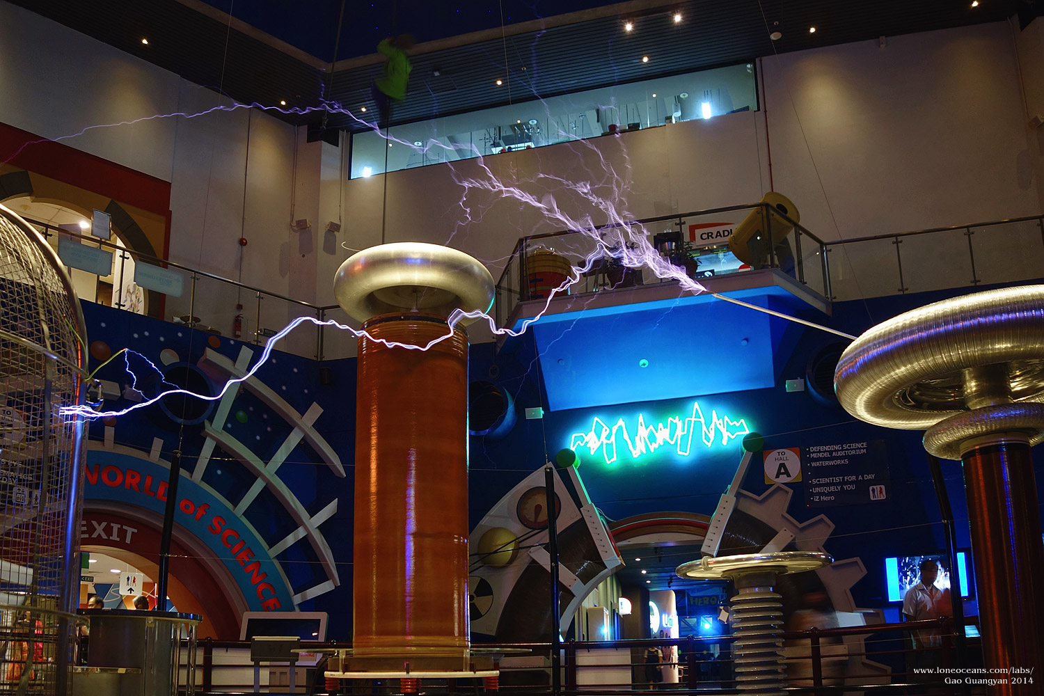
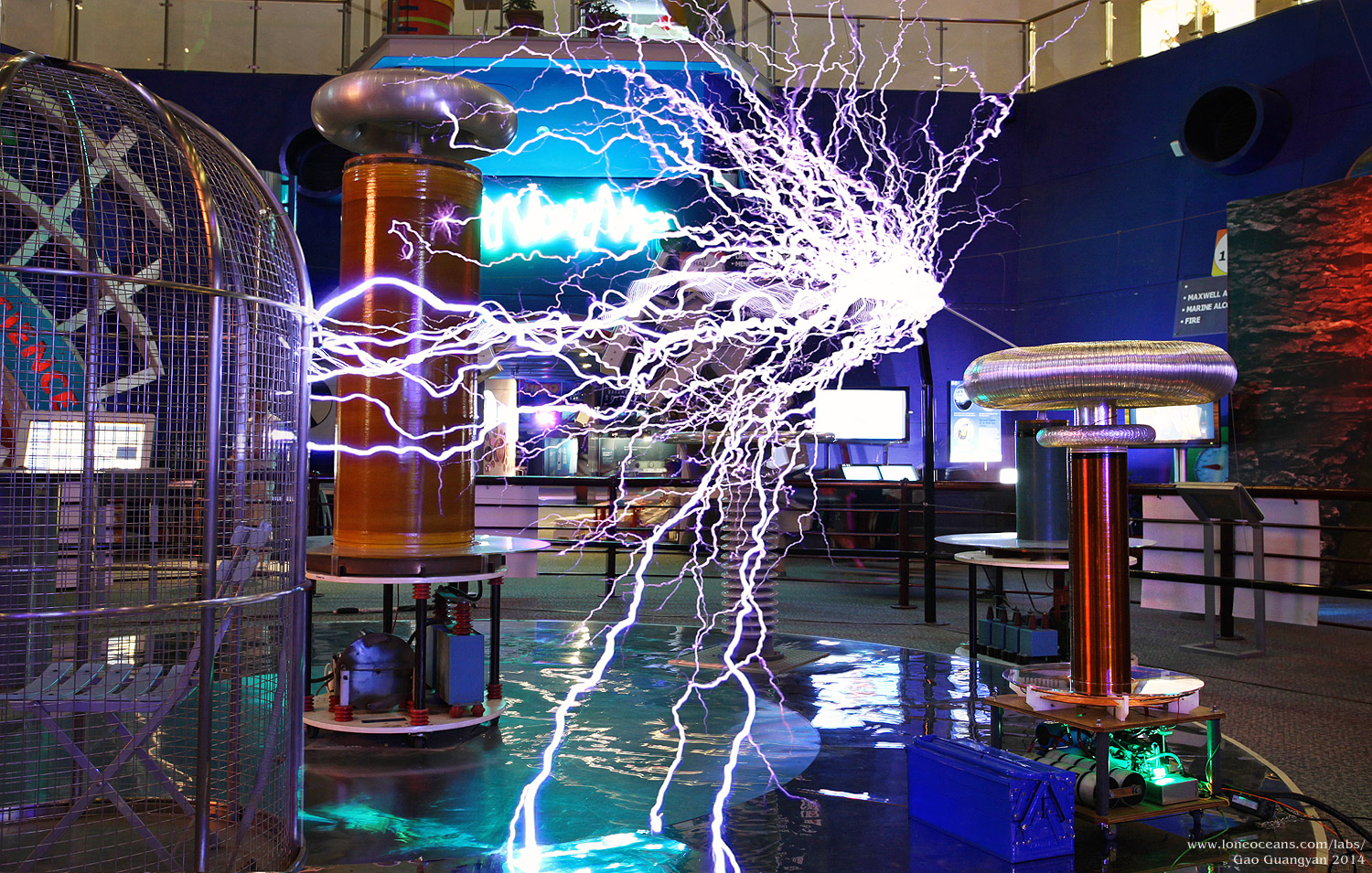
Power Testing - Final
In order to determine how far I could push the coil, the OCD was
increased from about 700A to 842A. This produced sparks
exceeding 7 feet at turn 5.58! Test were run at 625V on the
bus, with pulse widths at 70us and bps ~235Hz. Above shows
the coil easily making ground strikes and was in danger of
hitting the big coil (which it did several times!). The coil is
working beautifully with sparks just about the same as the much
bigger coil on the left! For reliability, the OCD was then
reduced to 700A.
At this point the coil is basically complete and I'm quite happy
with how everyone turned out.
As a prototype showpiece coil, the Science Centre and I decided
that it would be a good idea to run the coil conservatively, so
I the coil's OCD is now reduced to 700A running on a low ~180VAC
input. This still easily produces 6 feet sparks, more than 2.5x
the secondary length. I am now confident the coil will hold up
at higher power input producing even greater 8 to 9 feet sparks
in the future if we turn up the taps a little bit more!
The prototype coil is now in public display at the Singapore
Science Centre - a little bit more work needs to be done
regarding installation, but it should be ready soon!
Videos
Here are some videos of the coil in action during preliminary
testing playing MIDI files.
Pirates of the Caribbean - 185VAC, 20-25A, 700A, 70us.
Dance of the Sugar Plum Fairy - 180VAC, 1.6 - 3.2kVA, 700A,
70us.
Check out the coil in the Singapore Science Centre!
Credits
I would like to thank the following people for help and
inspiration for the coil!
Raptor, for lending me his portable oscilloscope in
helping test and tune the coil in Jan 2014
Steve Ward for some very good advice and suggestions
for the coil and in phase lead tuning
YX for helping me source and acquire suitable amounts
of magnet wire - a challenging task in Singapore!
My parents being supportive of the project and
tolerating the mess in my house while construction was taking place
The Singapore Science Centre and all the friendly and
helpful staff who has helped made this project so successful
All the great tesla coil websites on the internet which gave me valuable advice and construction details
And everyone else who has helped me in one way or another.
This coil remains as a fully functioning prototype
musical tesla coil in the Singapore Science Centre today!
Back to main page
(c) Gao Guangyan 2014
Contact: loneoceans [at] gmail [dot] com
Loneoceans Laboratories. Copyright (c) 2003 - 2014 Gao Guangyan, All
Rights Reserved. Design 3.
Removal of any material from this site without permission is strictly
prohibited and will result in infringement of copyright laws.
Disclaimer: Projects and experiments listed here are dangerous and should
not be attempted.
www.loneoceans.com/labs/
... page generated in 0.0001 seconds

 Page Contents