Ignition Coil Driver
High Voltage from a car ignition coil
12 Sept 2003
Introduction
So what is an Ignition Coil? An Ignition Coil is an induction coil that converts
voltage from a car battery (12V) into the high-voltage sparks
(several kV) required by the spark plugs in a car engine. An
ignition coil is a high voltage transformer at its heart, and comprises
of two windings (the primary and secondary), wrapped around a steel core
- just like a normal transformer! The primary coil consists of a few
turns of thick wire and the secondary, many many turns of thin wire.
There are several different kinds of ignition coils, but the most common
one is the cylindrical-shaped one, using a rod-like steel core, but they
all work via the same principle. Unlike normal transformers, ignition
coils create much higher voltages than usual, thus they are usually
encased in epoxy or oil. In older
cars, the ignition coil operates by a contact breaker in the car
periodically interrupting the flow of battery current through the coil,
in sync with the engine and specific to the number of cylinders the
engine has. Every time the contact breaks, the current is interrupted in
the ignition coil, and this collapsing current induces a high voltage in
the secondary. These days, solid-state transistors and electronics
replace this older technology due to its greater efficiency and
controllability.
The ignition coil works via
electromagnetic induction. When current is applied to the primary coil
(e.g. from the car battery), current flows through the coil and a magnetic field is created. However, when this current is removed, the magnetic filed collapses and this will induce a current on the secondary coil creating a high voltage spike.
In this way, an ignition coil is a pulsed device, but can also be
operated in various other ways.
One nice thing about car ignition coils is their robustness and
reliability - they are built to withstand the though environment near a
car engine, and therefore are very durable. In fact, instead of running
our ignition coil at 12V, let's bring it up one notch further :-).
Driver Circuit and set-up
So now you know what an ignition coil does, lets move on to the experiments.
The first step is acquiring an ignition
coil. They are relatively cheap new, but you can also get them for
basically free at your local car mechanic. There are two kinds of coils
- the cylindrical oil-filled types like the one I am using, or the more
squarish metal kinds, both of which will work. Our goal is now to create
a circuit which will periodically interrupt the flow of current in a
sudden and abrupt way. Fortunately we have a clever way of making this
work easily.
And above is a diagram of the very
simple circuit I used with only 3 components. One warning - because this
works off the mains, it is extremely lethal and utmost
care must be taken when running the circuit. The capacitor also stores a
lot of energy, and care must be taken to discharge the capacitor before
coming in contact with any part of the circuit.
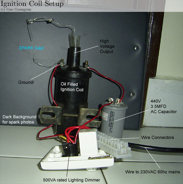
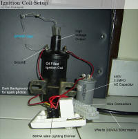
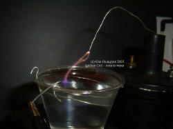
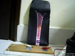
The photograph above shows how I've set
up my coil. I used a dark background to facilitate easier photo taking and spark viewing. The plastic thing on the top is my attempt at preventing arc over from the HV lead to ground.
The output is significantly higher than if run from a car battery (I'm
using the mains) so therefore I need better insulation. But how does it work?
The secret of this circuit is the dimmer
which contains a device called a triac. This is an electronic switch that gets triggered in sync with the mains frequency. The knob on the dimmer adjusts the timing of the trigger.
What it does it that it chops up the sine wave from the mains, as shown
above, by turning on and off (in both directions). This is the method
which also reduces the brightness of a bulb since it sees less overall
power. The way to think of this as a switch that opens and closes. Now
lets follow the steps on what is going on.
-
Lets assume the dimmer is set to
half way. At the beginning when the triac turns on, the mains
charges up the capacitor to about 240 * Sqrt(2) volts through the
induction coil's primary.
-
After a quarter wave, the voltage
goes to 0 and the current drops to 0, the triac turns off.
-
If you've set the triac to fire just
at the middle (50%), watch what happens. The mains is now at
negative 240 * Sqrt(2) volts. Suddenly at the peak of the (now
negative) since wave, the triac closes. Now across the capacitor is
suddenly twice 240 * Sqrt (2) volts, = 680V! This capacitor now
discharges through the primary coil with a huge current!
-
This surge in current (and later
collapse) creates a big changing magnetic field and thus induces a
high voltage in the secondary. This result is a big spark!
Now repeat this procedure 50 times a
second and you've got what looks like a continuous spark on the ouput!
Parts Needed
Constructing this circuit is simple. We only need a few components. You can get the ignition coil from your local car repair shop. Just ask them for one, and say you need it for a project. They might give you one for free or at a low cost. Of course don't expect to get a brand new one. It will be a used one and be prepared to wash the grease off! Another alternative is to buy a new one which
should be around $10 or so, unless you're getting a really good one.
The dimmer is quite straightforward - your local mart would have it. Go to the lighting section and find a light dimmer. The higher the rating, the better. (500W or above should be fine,
and ou wouldn't want to blow it and go back to buy another one). Finally, the capacitor: You need an
AC capacitor of anything from 0.1 microfarads to 20 microfarads, at any voltage from about 250-600V(depending on your line voltage).
Do NOT use an electrolytic capacitor. I recommend generic motor starter
capacitors. They all work, but the bigger the cap, the greater the output power. If the cap is too big, the ignition coil will overheat
and you run the risk of blowing your light dimmer. If the coil body gets too warm to comfortably hold in your hand, you need a smaller capacitor. Using my 440VAC 3.5 microfarad capacitor, it doesn't even get warm after a long use! The final thing you need are the wires, and connectors.
Proper Insulation
At these high voltages, insulation is
important. There are a few ways to insulate the HV terminal when the high voltage keeps arcing out from the terminal to ground. To have sufficient insulation, you must pay attention to creepage and clearance. Clearance is obvious enough, it is the distance of material between two conductors that will prevent breakdown of the surrounding material, causing some kind of conduction (around 1.1kV per mm). Creepage is due to arcs "tracking" along surfaces to reach their destination (i.e. from the HV terminal to ground, the arc follows the surface of the ignition coil top.)
The way to get around this is to increase the distance the arc has to travel. If you look at HV power transmission lines on pylons, you can see that the insulators are ridged
all around the sides of the body. This is to increase the path length the arc would have to follow, increasing the breakdown
creepage distance. One way is to try placing a piece of HV insulated wire in the HV terminal and then fill the terminal up with epoxy
or wax. Another way, is to cut a circle of plastic, protruding about 3cm, fitted over the top of the ignition coil. Holding it in place with a decent sized bead of bathroom silicone sealant all the way around (making sure there are no gaps) will prevent tracking around.
But a bit of silicone is missing, it will arc through the hole.
Electricity always takes the path of least resistance.
Experiments with Arcs
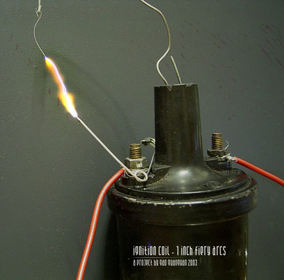 
Two different pictures. Lets take a look at the one on the left first. That's a 1 inch hot, fiery arc, made by pulsing a 250V 240uf charged capacitor through the primary. Sure it's only one discharge and it's not continuous arc, but now we know the coil works at least (this
was how I tested the coil before I bought the other components for the circuit).
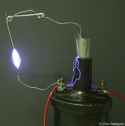
After wiring it up with my mains circuit... (second picture) This is a 1/2 second exposure so you can see the multiple arcs. Also notice some arcs creeping along the surface of the coil to ground (proves my lousy temporary insulation doesn't work), and the corona from the other point. Lots of
EM radiation is generated and every time I turn it on, and my TV display would
start to mess up... The voltage generated is very high, possibly over 30kV or
more based on how much spark I was getting!
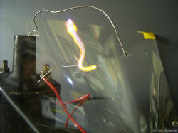
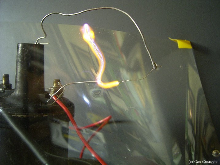
A hot arc snaking around a plastic sheet.
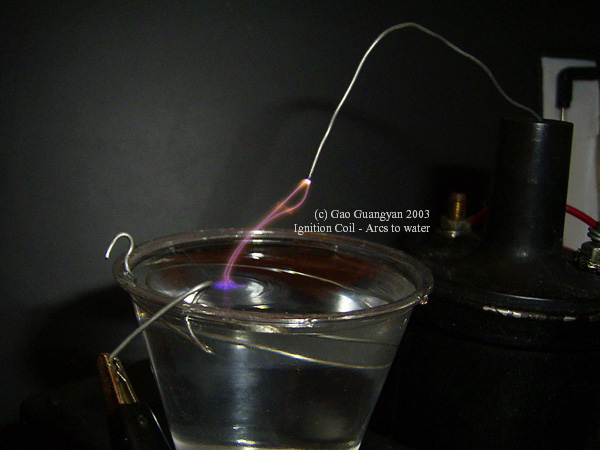
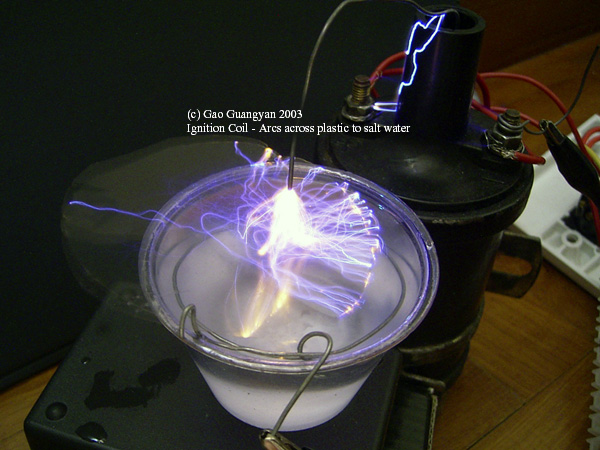
New pictures!
These are new photos not released before! First picture shows a short exposure of an arc arcing to a pool of water. Note the colours and the ripples caused by the arc. The second one is a 1 second exposure of arcs snaking around a plastic sheet to a pool of salt water. Click to enlarge.
Updates
11 Nov 2003
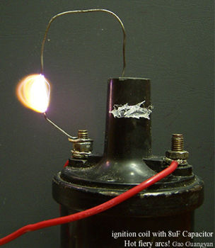
More power to the coil!
Instead of a 3.5uF capacitor, I upped it with a cheap 250VAC 8uF capacitor. (In case you were wondering, the white stuff is hot glue). The difference is quite obvious. Instead of thin blue arcs, they have changed into fiery hot bright arcs. There is clearly a lot more current in the arcs.
Compare this picture with the one above (with the bluish arcs) and see the difference. However, at this levels, the coil gets warm to the touch only after a while. The 3.5uF configuration allowed the coil to stay cool even when run for extended periods of time.
I plan to use a higher capacitance capacitor and see what happens... people have driven the coil up to 5000W! Ignition coils are built quite well and they are almost like small versions of Pole-Pig-Transformers/Power Distribution Transformers
you see up on wooden poles, and can supposedly handle quite large amounts of overrating and abuse
(they are, afterall, meant to work in the harsh conditions of a car).
Second Updates
2nd Jan 05
 More updates! I finally got around to do what I wanted to do
- twin coils. As you can see from the photos above, the the HV insulator
was obviously inadequate and the HV arcs over. This is seriously limiting my maximum arc length. I bought some 40kV wire (like those in flyback transformers) some time ago for $2 per meter and I haven't got around to using it yet. I also went out and bought some tea-light candles yesterday. More updates! I finally got around to do what I wanted to do
- twin coils. As you can see from the photos above, the the HV insulator
was obviously inadequate and the HV arcs over. This is seriously limiting my maximum arc length. I bought some 40kV wire (like those in flyback transformers) some time ago for $2 per meter and I haven't got around to using it yet. I also went out and bought some tea-light candles yesterday.
Look at the diagram on the left. I first soldered the 40kV rated wire to the HV output. Then I got a piece of PVC pipe (blue pipe in the diagram) and stuck it over the top of the HV terminal, and sealed the bottom with a generous amount of hot glue (light blue). The tube was then filled with melted candle wax (yellow) and left to cool. I did this to two of my ignition coils. Normal arcing will occur where the blue arcs are in the diagram.
Once completed, I plugged one coil in the driver as above (using the 3.5uF cap) and I got amazing results! However there were arc-overs at the bottom of the PVC pipe (indicated by the green lines at the diagram) if I pulled the electrodes apart too much.. looks like the voltage is too high! (which is good :-) )
To get even higher voltage, it is possible to wire 2 coils in anti-parallel for twice the voltage. I wired the two coils in anti-parallel (the + of the first coil is connected to the - of the other coil and the arc strike between the two HV outputs.) and the result was spectacular. I had attempted this previously but arcing problems limited a maximum of 6cm arcs before arc-overs got too serious. This time, I managed a 10cm long continuous arc! That is at least 100kV but limited by insulation break down. Looks like I've got to put these coils in oil.
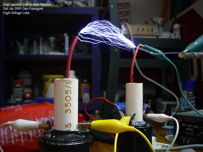
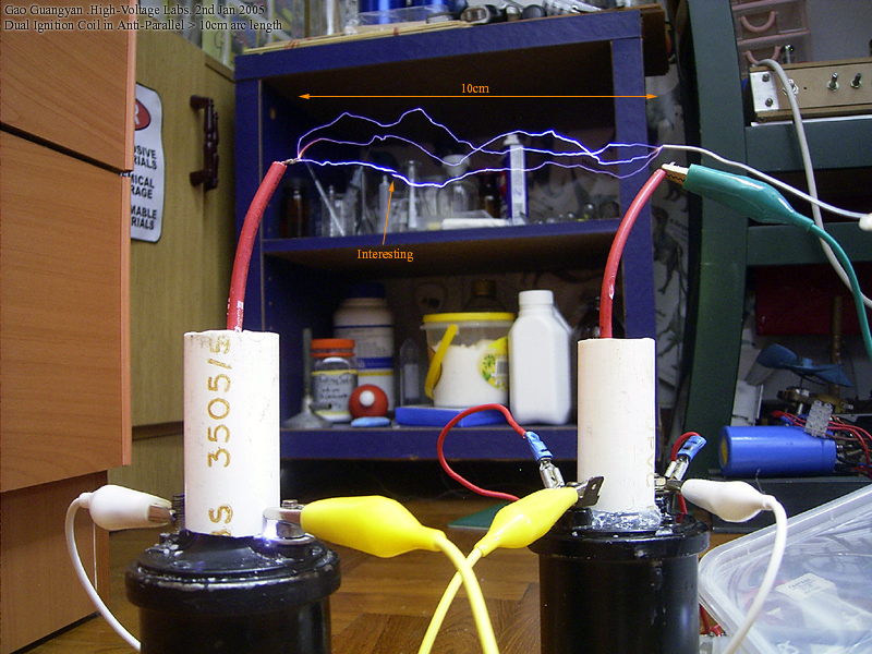
The photos above show my achievement. The first
photo shows arcing at 6-7cm distance. The second photo shows the 10cm arcs.
There is a arc which seems unconnected in the photo. I'm not sure what is
causing it, but it is probably due to the CCD read-out of my camera's sensor,
just missing the spark at the end of the exposure.
In the future I might get two better coils and enhance my driver circuit to achieve even greater spark length. I can enclose everything in a clear acrylic container and fill it with good transformer oil. This will stop the arcing over and insulation problems once and for all!
Other Experiments
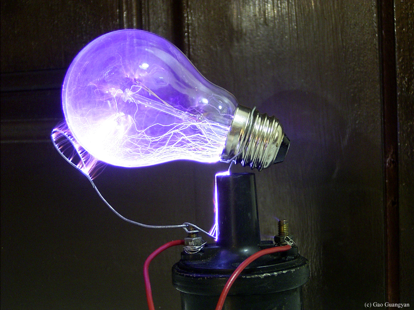
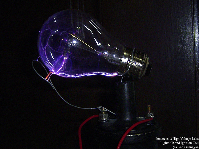
Experiment with 'Plasma Globes'
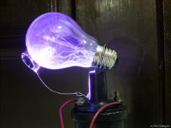 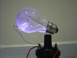 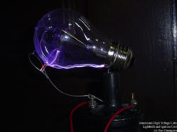
After my experiments with flyback driven plasma globes, I decided to give a try by hooking up a light bulb to the HV output. It won't work like a plasma globe due to the low frequency, but I expected spectacular results. The pictures have proved me right! This is a
Loneoceans must see picture! (click the thumbnails now) There are arcs inside and outside (the surface) of the bulb. Also notice the arcs from ground (the loop of wire) to the bulb. In real life, the arcs are much more purple, most probably due to the low-pressured nitrogen in the bulb. A video is available for download. (Scroll down)
Experiment with the Jacob's Ladder
 If you were wondering if this ignition coil can power a Jacob's ladder, the answer is yes. If you were wondering if this ignition coil can power a Jacob's ladder, the answer is yes.
On the left you can see a 1 second exposure of the the jacob's ladder. The increased power I get from this coil allows me to build a much bigger and taller jacob's ladder than the flyback driven one. This picture shows the arcs starting from the bottom and moving up to the top, extinguishing, and starting from the bottom, just like those science-fic movies in the past, just that mine is smaller. It makes a loud bzzzzz sound as it goes up and after a short use. Ozone production is higher and the wires get much hotter than the flyback driven ladder.
Compare with my flyback driven one and you can see how much nicer this one is :) Just look at those arcs.. If you coat the wires with salt, the result is a bright yellow arc. It has a plastic base, with two wires duct tapped on it, and bended in a shape of a "V". One side is high voltage and the other is ground. The jacob's ladder is very much affected by even the smallest wind, and precautions had to be taken to make sure the wind didn't blow it out before reaching the top of the 'ladder'.
Videos
Here is the video of the sparks and the plasma globe in action!
(you need Windows Media Player to view the videos which are encoded in WMV format)
Ignition Coil in Action and with bulb attached: ignition.wmv (799kb)
Updates: 1st Feb 2004, 7th June 2004
Back to main page
(c) Gao Guangyan 2011
Contact: loneoceans [at] gmail [dot] com |