A Certain Shade of Red
A Physics Land Yacht competition 2006
A Project with Nicole Quah, Cheryl Quah and Daniel Lo.
02 Feb 2006
Preface
This project started on 02 Feb 2006 when I was 16 years old as a JC1 student in Raffles Junior College. The final project report is reproduced below almost verbatim, and documents the project quite comprehensively. As for the actual construction process, I quote from my journal (with some edits):
Today for physics we were told of some building thing, which we have to build some land yacht. Similar to Mr. Lim B. H's physics projects, but I think it's not as a good. For one they tell you not to make your own wheel holes (they provide some white bottle caps) because they think a whole group of the smartest 16 and 17 + year olds in the country can't safely handle Basic machining tools like drills, and cannot drill holes properly. Anyway, it's wiser to drill a hole first than to make a wheel, because that's what people mostly do, even with CNC'ed wheels! And do you really trust the lab people to drill accurate holes (they have to, after all drill hundreds of holes dead centre of circles)? So I think my group shall make the wheels ourselves :). Saves them some trouble too.
I formed a group of 4 with some classmates, and on 5th Feb 2006, I started doing some proper research...
Was doing some research on the Physics land yacht. Actually if it was to make an amphibian vehicle it would be a lot cooler, but no we are just doing it on land, which is not very exciting. Anyway, there is a lot to read about sails and how to make it as efficient as possible. So actually if you take it seriously, it's not exactly very easy after all... but using a fan to generate wind is actually a very bad idea due to the mechanics of how the sail works.
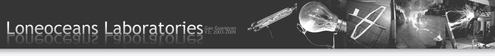
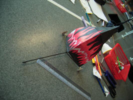
06 Feb 2006 was when I made the first prototype, as you can see in the photograph below. It has a very skeletal construction and was perhaps, a bit too elaborate. Used a good number of bamboo skewers, novel techniques to shape them (e.g. fire to bend the wood for the chassis) and a very light (but flimsy) sail made out of clear wrap.
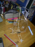
Today I made a prototype for the physics land yacht thing. So far it looks promising, but I can't post the details here. It moves in a light breeze  . Still have lots to improve .Took quite a bit of time to make Ugh. Need to do my other work now and I'm really sleepy. . Still have lots to improve .Took quite a bit of time to make Ugh. Need to do my other work now and I'm really sleepy.
10 Feb 2006
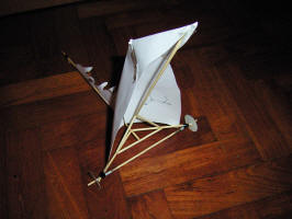
Today I rebuilt a 2nd prototype for the physics land yacht with an improved chassis design, using a grand total of 4 satay sticks including the axle. I used a heavier simpler less efficient paper sail (temp) but it still performs mighty well. Flies when using a Delta Focused Flow 120mm DC fan! Design looks more promising, and it's easier to build. Still can't figure out some things regarding sails. I think my chassis design is actually not too bad.
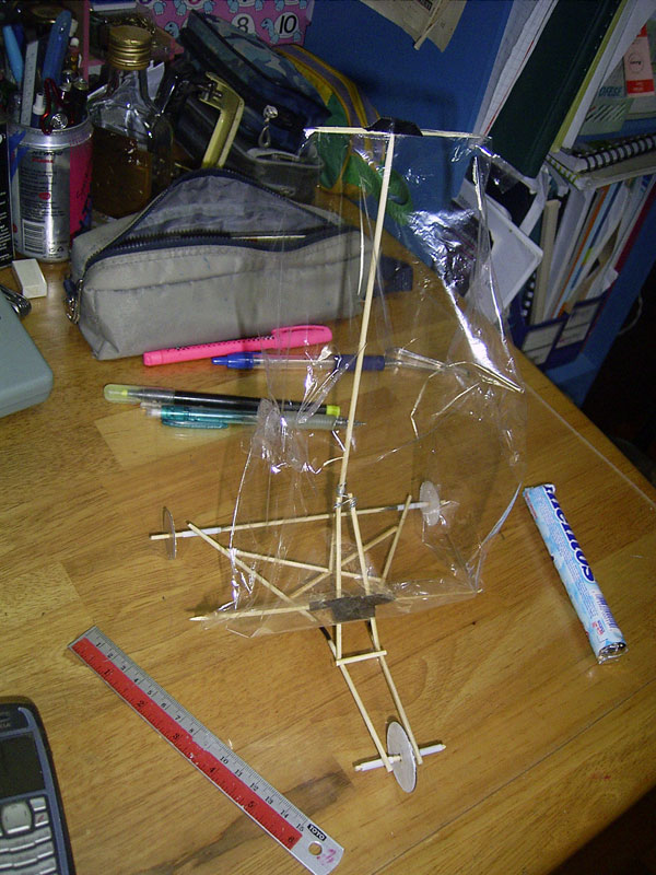
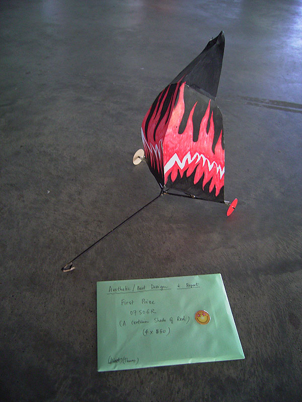
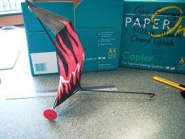
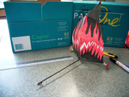
Having got the land yacht design more or less finalized, I built the final model on 12 Feb 2006, and started working on the aesthetics and project report. The final model is as below.
Note that I replaced the front wheel with a skid, shifted the sail back, and added a flaming paper decal.
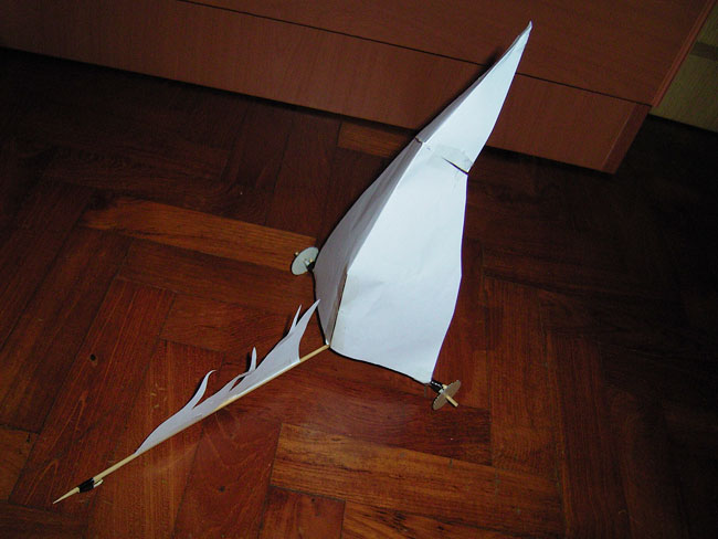
17 Feb 2006 - The Competition (Building part) Day! Although I had already worked on 3 models, the competition required us to build the actual yacht model at the physics lab in a specified time under specific conditions. As I recall..
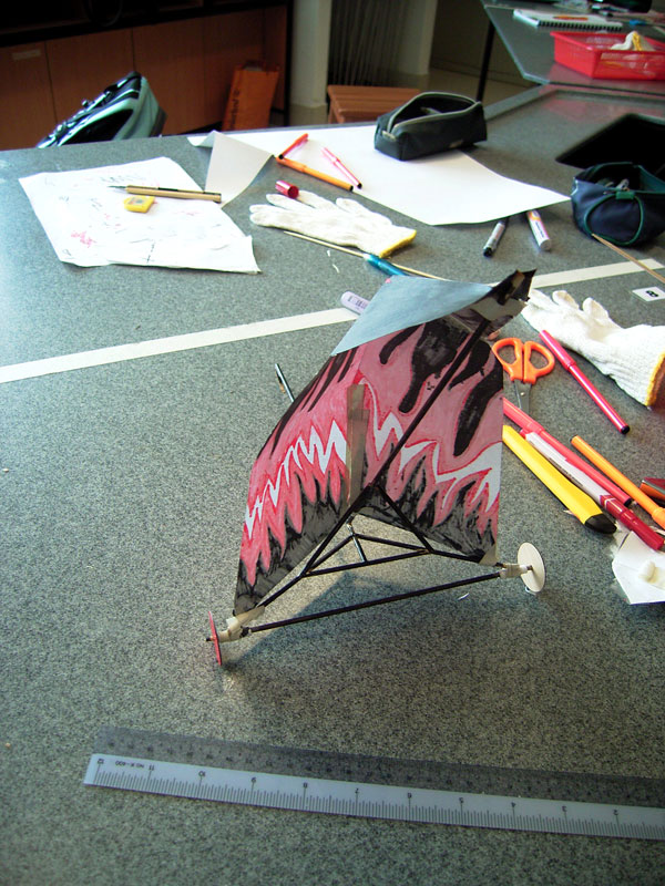
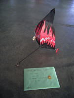
Today was the Physics land yacht building competition. Since we had planned it quite ok and I had built 3 models already, it was a rather easy task building it. So we spent about 1hr trying to make it look nice. I didn't have enough red ink so in the end I ended up with this paint scheme which I think looks reasonable ok. And check out those flaming hot wheels! Anyway, we spent a whole lot of money (800) though we had a quite a bit of extras leftover.
I think it is possible to use some crafty method to make the yacht incredibly cheap and travel a medium distance, yet winning a the competition because of the loopholes in the calculation (distance traveled over cost or something like that). But then that's not the point in the competition. Penetrating power is not exactly very good for ours but I tried to minimize it by using an effective sail shape (hopefully). Decided to use a skid for the front because due to the nature of the design, the force exerted on that part is low, and hence unless a very efficient axle/wheel is used, the wheel might not even spin and hence still act as a skid, while increasing weight. The second advantage is that once the craft decelerates from drag of the sail, the design will case a rotation about the main axle and hence reduce force on the skid, hence reducing friction. But anyway, I'm happy with the design (though less than ideal) and the aesthetics (which we spent quite a bit of time doing). Yacht name is... A Certain Shade of Red! Perhaps if we're lucky we can win!
And by right everyone should have had finished building their yacht. So if you happen to have not built it yet hopefully you won't try and copy the design because then it's not fun and not the point anyway right? =).
24 Feb 2006 - Competition Day
The first half of Physics practical was spent having a tutorial, before we proceeded to a room called Space 1 (I think) for the physics yacht testing. After having heard of how the testing was like, I had quite low expectations for our craft, because it was designed exactly not for the competition (just a fan blowing at it), but rather as a real land yacht with constant wind. Expected to go about 4 metres. The test floor was also much rougher than I expected, but in the end, I think it did quite ok and went more than twice of my expected, which is good. Wasn't disappointed in that (8+m, versus 11+ which some others acheived), but was slightly disappointed that I didn't actually consider how the testing would be like and designed the craft for the competition itself (but it's not exactly the point). Perhaps thinking too much isn't really helpful. But now I do have some great plans on how to make a very good craft that would efficiently perform in that competition setting. Anyway. But I think my craft A Certain Shade of Red does look rather nice. And I still like my design. We learn everyday.
02 Mar 2006 - Results Day
We had the Physics prize presentation for Physics.. and it was rather funny how the physics lecturer said that our project report seemed to be written for a scientific journal, and how the design was so comprehensively thought out. And surprise! Our class did pretty well. Nike got a commendation prize, and A Certain Shade of Red got Best Design and Report prize of $200! Unfortunately they were Borders vouchers.. I would have preferred cold hard cash. But anyway, it was fun!
So this is the story of my little land yacht project! And as mentioned above, here is the project report:
Project ReportINTRODUCTION
In this project, we were faced with the challenge to design and build a land yacht, with size (to fit inside a paper ream box for 2500 sheets), material and construction (must be constructed inside the physics lab in 2 hours) limitations. A land yacht is a vehicle that moves on land and is entirely propelled by wind. The main performance will be characterized by 3 main techniques (competition): Distance [distance traveled when propelled by a fan], Distance per cost [cost effectiveness, since we will need to 'buy' the materials], and Aesthetics. Hence a few goals were set to achieve these as well as possible:
1. Design of chassis and sail will be as aesthetically pleasing as possible
2. Materials used will be kept to a minimum, to reduce cost
3. Made to travel as efficiently as possible, as a land yacht model
Materials provided are as follows: bamboo sticks, ice-cream sticks, light string, straws, super glue, scotch tape, sail material (plastic, paper, aluminium foil). Most efficient use of the materials is important to reduce cost, and yet being beneficial to the performance characteristics of the entire vehicle.
DESIGN
Main Chassis Design
In order to make a most efficient design, the chassis would have to be designed as efficiently as possible. After research, it was noticed that most designs were similar, with 3 main contact points – two rear wheels and a front wheel. Three points define a plane; hence to reduce weight, a chassis with 3 contact points was designed from the beginning. The chassis had to be as stable as possible, and include a mast. In order to maximize efficiency, the chassis was designed to fit just under the size limit. In order for the craft to be stable, its base area was designed to be as large as possible. Hence the main axle length was made to be 20cm long, with the 3rd point as far away as possible from the rear axle. After some consideration, a minimalist design was created to be as strong as possible, yet using as little material as possible.
Material choice of the chassis was limited to bamboo sticks, ice-cream sticks and straws. Bamboo sticks were chosen for their exceptional material properties (light and strong), and material dimensions (they are long, hence does not require joining unlike ice-cream sticks).
Once the chassis was created (diagrams below), a mast had to be attached. The mast was placed near the rear of the base, this provides greater stability compared to a yacht with the sail situated close to the front, because a much greater force would be needed to provide sufficient torque to tip the yacht over about its front end (which would act as the pivot point in that case). The chassis had to be made as rigid as possible – flexing is detrimental as energy would be spent flexing the members instead of accelerating the vehicle. Hence the use of triangulation was used extensively in the minimal frame, resulting in a very strong, rigid yet lightweight frame. By Newton’s second law a = F/m. Hence given a force of equal magnitude, a less massive vehicle will experience greater acceleration, allowing it to reach greater speeds and hence cover more distance in a shorter period of time.
Vehicle Component Design
Sail Design
Before designing the sail shape, research was done to find out how competition land yachts had their sail designed. It was discovered that sail design was a main factor in yacht performance. A well designed sail can accelerate a vehicle to almost three times the speed of the wind due to an airfoil shape which creates a low pressure at the front of the sail. Most land speed record sails were rigid, thin and high, and were most efficient in constant strong wind. However, these required precise sail shaping and acceleration was slow (though with high top speed). We were constrained by materials and hence a different option had to be taken.
While sailing downwind, water yachts frequently deploy an extra sail specifically for use in downwind, called a Spinnaker. It resembles a parachute somewhat in both construction and appearance, and when deployed, it fills with wind and balloons out in front of the boat. One main difference when compared to a normal sail is that a spinnaker is a type of airfoil and does generate lift. Lift and drag generated by the spinnaker act both to move the craft forward; hence lift-to-drag ratio is not important. The goal is then to generate the maximum possible lift with no consideration of drag. Hence most spinnakers have extreme amounts of camber, making them nearly hemispherical in form. The large camber maximizes the low pressure on the downwind side of the sail, generating the lift.
Material Choice of the sail was limited to aluminium foil, mahjong paper and plastic sheet. The lightest material was chosen for the sail to reduce the overall weight of the yacht. Hence paper was chosen as it was the lightest per surface area, cheapest, and easy to decorate (aesthetics). With the same net force acting on a lighter craft, there is greater acceleration, and speed is enhanced. The general shape was triangular with a smaller sail area at the top of the yacht. This will lead to improved stability under strong wind. We tried to make it as similar to a standard spinnaker design as possible. A vertical half-fold was made and further cuts and folds were made (refer to physical model), giving the sail curvature, resembling an air-foil.
Although in a general case scenario, a land yacht is supposed to be designed to move in constant uniform wind, not a strong but decaying wind from a fan. That means the wind strength will decrease as the craft is further away from the wind source (during competition). In order to better satisfy the greater distance performance test, drag of the sail was designed to be minimal. Air resistance is a force opposing the motion of the yacht, reducing the net force acting on it to move it forward, and hence slowing it down (a = Fnet/m); the larger the surface area of the sail, the greater the drag/air resistance experienced by the yacht. Thus we did not set out to make the sail as large as possible. Furthermore, the vertical fold along the middle of the sail gives it a “cutting” edge, allowing it to “cut” into the wind, i.e. air meeting the edge travels smoothly over the surfaces on either side of the fold (similar to an airfoil). In this way, drag is greatly reduced, as opposed to a sail with a full surface perpendicular to the wind.
Wheels, Axle and Bearings
An important factor in efficiency was to reduce the energy losses in due to friction. All moving parts were designed to be as efficient as possible (low friction). Wheels were made using a thin but stiff laminated wood sheet, which exhibited excellent rigidity yet being light and strong. Having lightweight wheels is especially important because the weight of the wheel has to be accelerated both forward and around its centre. Also, Fs,max=μsFN. Hence, wheels/vehicle of smaller mass would experience a smaller normal force and hence lower Fs,max. This will lead to increased acceleration with the same amount of force applied.
After experimenting with some designs, it was decided that a skid was to be used for the front of the vehicle instead of a wheel, because due to the nature of the design, (where the main body of the yacht is situated towards the back and the front consists solely of a long shaft,) the force exerted on the front end of the vehicle is low. Hence unless a very efficient front wheel is used, it might not spin, thereby acting as a skid while increasing weight. [This was verified experimentally. Furthermore, it was difficult to construct brackets to support the front bearings without adding significant weight, which will increase weight and construction time]. The second advantage is that once the craft decelerates from drag of the sail, the design will cause a rotation about the main axle and hence reduce force on the skid and reducing friction.
Bearings were made using rolled paper tubes. This was possible because our sail was to be made using paper, hence leftovers were used to make the paper tubes. To reduce friction, the bearings were made a short as possible, 1.6cm long. To reduce bearing and axle friction, graphite from a 6B pencil was used. Axle was made using a single bamboo skewer.
Aesthetic Design
Aesthetics is no doubt important. Since the entire yacht design is very minimalist, there is very little of the structure to decorate, except the bamboo members of the frame, the sail and the wheels. The name of the yacht was decided to be A Certain Shade of Red, with primary colours being black and red. The wheels were coloured bright red using a marker, and the frame coloured black. One advantage of the sail being made of paper allows it to be easily coloured using markers instead of paint, which is heavier. A red black and white flame scheme was then applied using markers to the white sail with good results, yet not significantly increasing weight.
CONSTRUCTION
Chassis Construction
Since the entire mainframe is made using bamboo sticks, one of the most important factors in ensuring frame rigidity and strength lies in the joining of the different structural members of the structure. The structure is only as strong as the weakest link, which more often than not, is the weakest joint. The adhesive material of choice is Cyanoacrylate superglue, which is a strong acrylic resin. In order to create maximum bond strength, contact surfaces were cut to have a maximum flat area (such as joining at angles, whereby the ends of each bamboo stick are cut to the exact angles to ensure a flat bonding surface), and hence maximum area for the glue to bond. Although time consuming, it proved to be an important factor in ensuring greater structural strength. Hence less material would be needed to be used.
[Please refer to diagrams below] The main base was constructed using a single 258mm long bamboo stick. An 85mm stick was glued perpendicular to one end of the stick at the middle, with two 105mm sticks originating 21mm from the end of the long stick, acting as the main lateral supporting structure. A 255mm bamboo stick was glued 31mm from the end of the long stick at a 63 degree angle, supported from the sides via two 70mm sticks. The main axle was a 198mm stick which was affixed to the ends of the lateral supporting limbs using a bit of tape and superglue, via paper bearings. The complete craft, including the axle, required 936mm of bamboo stick, or roughly 3.7 stick lengths (each 10 inches), which is very economical (sticks come in packs of 5). This results in a very lightweight craft (efficient) and economical, satisfying two of our goals.
Wheel, Skid and Bearing Construction
Wheels are very important as a perfect circle with a true centre is required for the smoothest possible travel. Wheels were first cut out from a stiff laminated wooden sheet. A 2mm hole was drilled. The wheel was then attached to a mandrel and spun at 15,000rpm using a rotary tool. Sandpaper was then used to grind the wheel down until it was as perfectly round as possible. Both wheels were grinded down at the same time to ensure that they are of the same size. The hole was then subsequently enlarged using a pointy grinding bit to fit on the axle tightly. The wheel was then glued to the axle using a small amount of cyanoacrylate. The completed wheels are 31mm in diameter. Bearings were made by rolling up a 60 x 16mm wide strip of paper, which was first rubbed with a large amount of graphite from a pencil to act as a lubricant. The result is a relatively smooth running axle. The skid was made using a small bamboo stick triangle, with a strip of bamboo acting as the main skid. Lubrication is done using graphite.
Sail Construction
The sail was made from paper. An isosceles triangle with base 240mm and height 275mm was cut out. Three triangles (refer to scale drawings below) were cut out, and the paper folded and then taped together, to form a curvature. As few cuts were done as possible to reduce weight gain, as taping the edges together requires more tape. The sail is then affixed to the chassis. The top of the sail was taped and glued to the top of the mast, while the other two edges were connected to the ends of the lateral limbs, near the wheel bearings. Effective sail area is about 300cm2.
Total Materials Required:
- 93.6cm of Bamboo Stick (~3.7 sticks)
- 300cm2 of Paper for sail
- 19.2cm2 of Paper for bearings
- 6B pencil (graphite) for lubrication
- Cyanoacrylate Superglue
- Small amount of tape
- 2 Wheels, Bamboo skid
- Decorating materials (markers)
DISCUSSION
Before the actual model was made, several test models were also built to find out if there were any major flaws in the design. Due to the low weight of the vehicle, yet large sail area, the craft was able to catch a lot of wind (force) and because F=ma and m is very small, the resultant acceleration for our vehicle was great, and also lead to a high velocity because v = u + at. Hence our craft was both fast, and quick to accelerate. The simple symmetrical design also contributed to the fact that the vehicle travels straight. This is beneficial in the test whereby a fan is used to generate wind. The only drawbacks in our design are that the skid is only good for certain surfaces, such as smooth concrete floors. Secondly, the craft’s low mass also results it being able to slow down quickly. Taking force F to be drag, the resulting deceleration from drag (once the craft travels far from the fan) is also rather large. To solve this problem the entire yacht could be made heavier, but then initial acceleration will be affected. However in normal land yachting, wind is supposed to be kept constant, and not like a table fan, whereby the wind decreases away from the fan. We have taken measures to reduce frontal drag (as mentioned above). Therefore vehicle performance will increase in a constant uniform wind. .
DIAGRAMS
[Figure 1 - Different views of the completed design]
On the left are simplified non to scale diagrams of the craft design, showing the top view,
side view and a three dimensional view. The actual vehicle dimensions differ slightly, but
have the same basic design.
Black: Wheels
Brown: Main Frame
Green: Mast + Supports
Blue: Axle
Red: Sail
Grey: Paper Tube
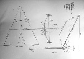
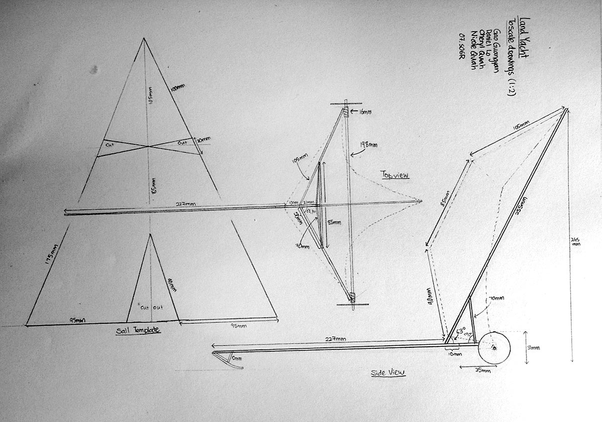
[Figure 2, Scale Blueprint Plans]
Above is an accurate 1:2 scale technical blueprint of the actual yacht model (including measurements),
including to-scale drawings of the sail plan as well as top & side design layouts.
*My scanner isn't working at the moment, so I just took a photograph of the plans*
PROJECT CREDITS
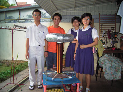
Team Members: From left to right: Daniel Lo, Gao Guangyan, Nicole Quah, Cheryl Quah
Done by Gao Guangyan, Daniel Lo, Cheryl Quah and Nicole Quah of class 07S06R of Raffles Junior College, Singapore.
Physics project report – land yacht building competition 2006. [Project Report: 23 Feb 2006]
First complied on 08 December 2008, Monday.
Back to main page
(c) Gao Guangyan 2011
Contact: loneoceans [at] gmail [dot] com |