Designing and building a simple Analog Music
Visualizer
via the Sallen-Key active filter
topology
A music visualizer
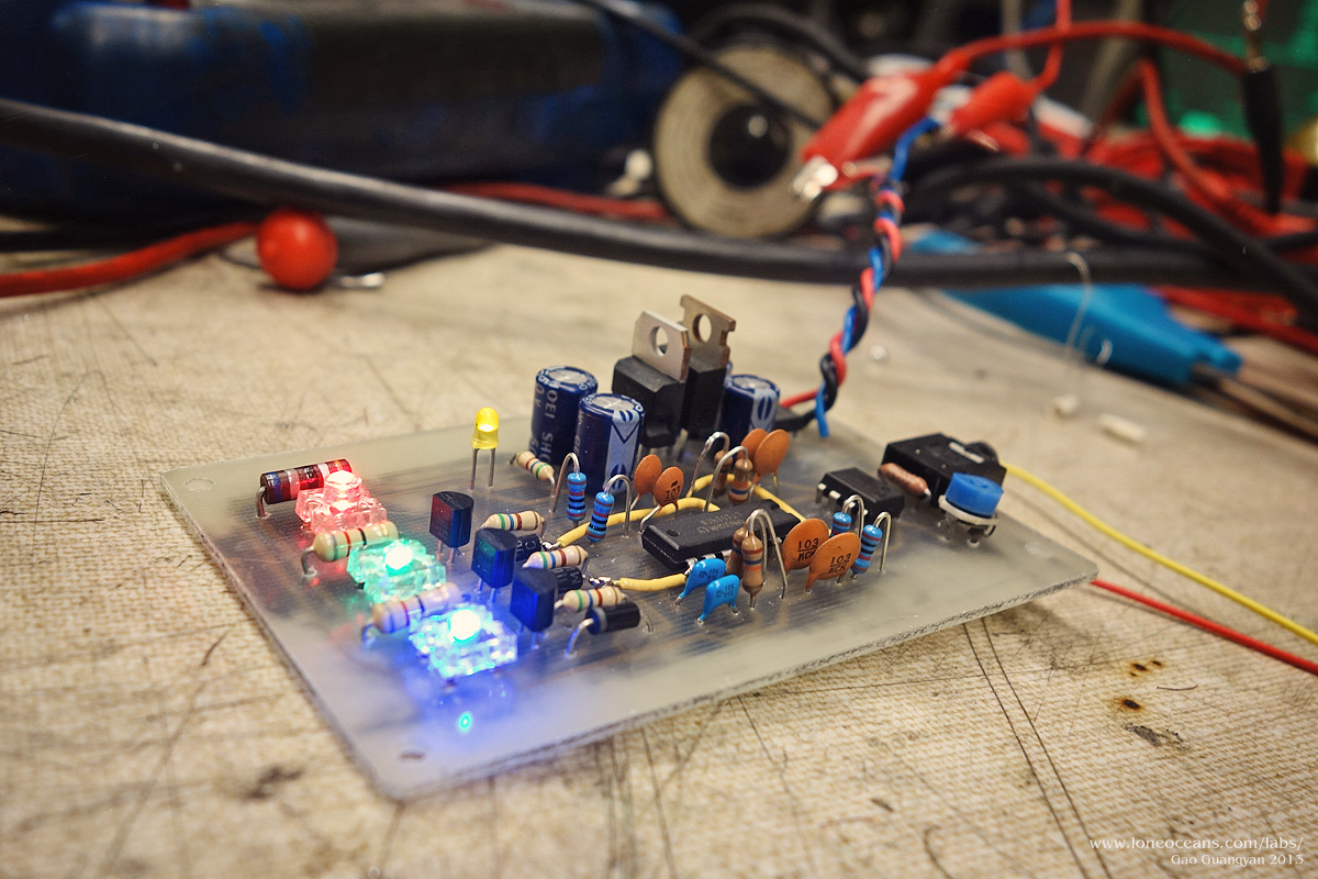
A simple 3-LED analog music visualizer - accepts a stereo input such
as from a computer or MP3 player.
You might have seen a project I did a while ago - an Arduino based
microcontroller musical lighting system which made 6 bright LEDs dance
to music. Check out the project page here.
That project was quite successful, but it used a microcontroller! In
this project, I investigate how to make a nice little music visualizer
similar to my digital one, but this time using only simple components
(op-amps and passives). The goal - to drive 3 bright LEDs, and make them
dance to music! This page outlines the design process and construction
of this little project.
Thank you for visiting my page and if you have any questions, wish to
share your projects, or feel that my projects have inspired you in one
way or another, feel free to contact me at loneoceans[at]gmail(dot)com.
Nov 2013
Introduction
Creating a music visualizer is a simple task. Our goal
is to separate our input music source into separate frequency bands.
Then, depending on the amplitude of each band, we light up an LED
correspondingly. Thus on a deep bass note, the low frequency band shows
a high amplitude, lighting up the corresponding LED brightly, while the
mid and high bands have a low amplitude and their LEDs do not light up.
The trick lies in creating a suitable filter for the
different frequency bands, and then using this information to control the
brightness of some LEDs. In this project, I have opted to create a
visualizer with 3 bands - bass, midtones and high frequency, each lighting
up a bright Red, Green and Blue LED respectively. The goal of the project
is to create a simple circuit to do this using on Op-amps and passives
(resistors, capacitors), and with a + - GND 12V power supply.
Creating a Filter - Sallen Key Filter
From our input music source, we seek to create a
high-pass, low-pass and band-pass filter. A simple low-pass filter would
be an inductor, and like-wise a capacitor for a high pass filter.
However, simply using these devices leads to a poor frequency response.
An ideal cut-off filter should allow frequencies above/below the cut-off
frequency to pass/block through - but this is challenging to create in a
simple device! It is important to make a good filter otherwise we will
have poor contrast in our dancing LEDs.
Enter the active filter. Active filters have a much
better response compared to a passive filter (like a simple RL or RC
circuit), and therefore are more suitable for making nice contrasty LED
lights. The topology I have decided to use is a Sallen Key filter, due
to its simplicity and effectiveness as a second order filter.
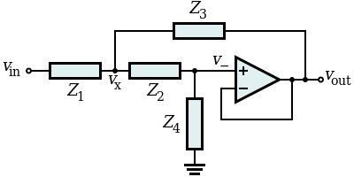
Above shows a generic Sallen Key topology with its
associated gain from
wikipedia.
The article describes the system a lot better than I can so I shall not
repeat what is being said. Suffice to say, the filter can easily be
created by adjusting the Z component values (R or L), creating a
suitable high-pass or low-pass filter. Two of them can be chained
together to then create the bandpass filter.
What Frequencies to Choose?
Based on my previous microcontroller lighting system, I
found that the fundamental voice frequencies of people to be around 150
to 400Hz, and I wanted to make the middle band LED respond best to human
voices. The low band will then be for bass, and the rest for the higher
band. Based on this, I decided:
Low Band: <100Hz
High Band: >800Hz
Mid Band: 100-800Hz
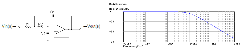
All that remains is to design the suitable Sallen-key
filter. Here's an example. For the low-pass filter with a cut-off
frequency f_c of 100Hz, I can choose the Z components to be 16K
resistors and 100nF capacitors. This gives me an actual f_c of 99.47Hz
with a Q of 0.5 and a response of around -40dB/decade!
As you can see in the frequency response graph, V_out is
attenuated significantly as the V_in frequency increases from 100Hz. The
same process was then applied to create the high-pass filter, and the
two filters in series for the bandpass filter.
Driving the LEDs
We can simply use the amplitude of the output voltage to
then drive an LED. There are several ways to control the brightness of
LEDs, and the easiest way is perhaps using Pulse Width Modulation or PWM.
This is because using a voltage to adjust the brightness of LED is
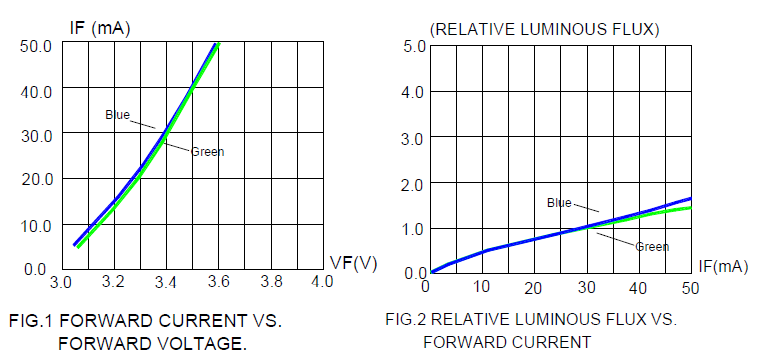
tricky business. Looking at the datasheet reveals why:
Above are two charts from the LED's datasheet that I
will be using. Notice high the current drawn by the LED increases
significantly within a small 0.4V window. It will be very challenging to
adjust the brightness of the LED in this small range, from our musical
source. Instead, a better idea is to use current to adjust the LED
brightness! Notice how the relative luminous flux increases more or less
linearly with current. We can exploit this by modulating the current
sent to the LED using our musical source.
Enter the transistor. As we know, the standard BJT is a
current amplifier when driven in linear mode, and the DC current gain is
given by h_FE in the datasheet. I decided to use the standard 2N3904 NPN
BJT, which has a varying gain of 70 to 100 at I_c from 1 to 10mA. It's
somewhat unusual but we can use this fact as a current modulator to
drive our LEDs!
Now we have all the parts present to build our
visualizer.
Design & Schematics
Nov 2013
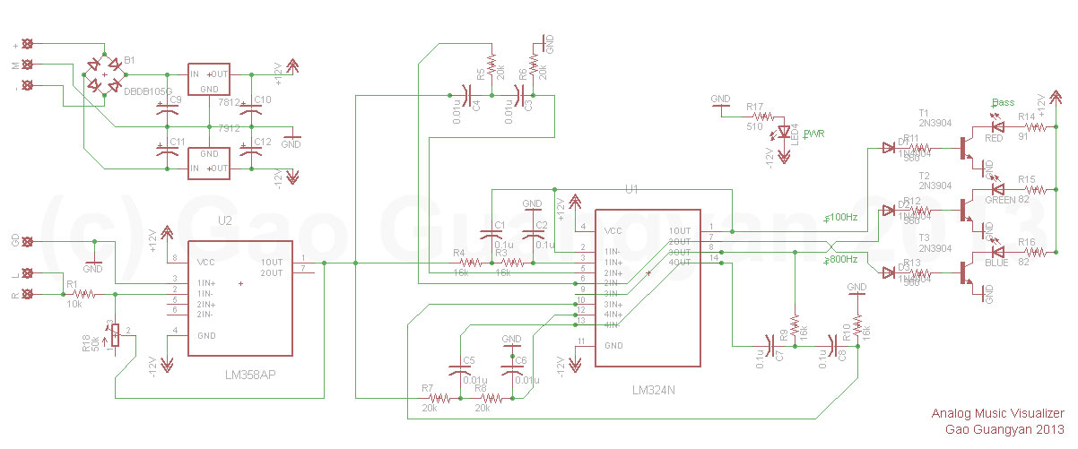
Below shows the complete schematic of my simple
3-band music visualizer. Lets see how it works.
Our input (R, L, GND) comes from a stereo female
jack. We connect R and L channels together since we don't really
care about that. The output is an AC wave aound +- 0.4V or so,
depending on your musical device. I decided that it should be
good to include some sort of volume control, so the first Op-Amp
acts as an adjustable gain of about 1 to 6. This amplified AC
musical signal is then sent into the V_ins of the 3 filters.
Notice I used a single quad-op-amp chip for the 3 filters (the
band pass requires two). The filtered signals get rectified, and
are fed to the base of the transistors. The base resistors limit
how much current flows. This is amplified by h_FE which
modulates the current flowing through the LEDs. The 91/82 Ohm
resistors act as a max current limit.
Finally, another yellow LED serves as a power
indicator, and a 7812/7912 pair acts as regulators for the + -
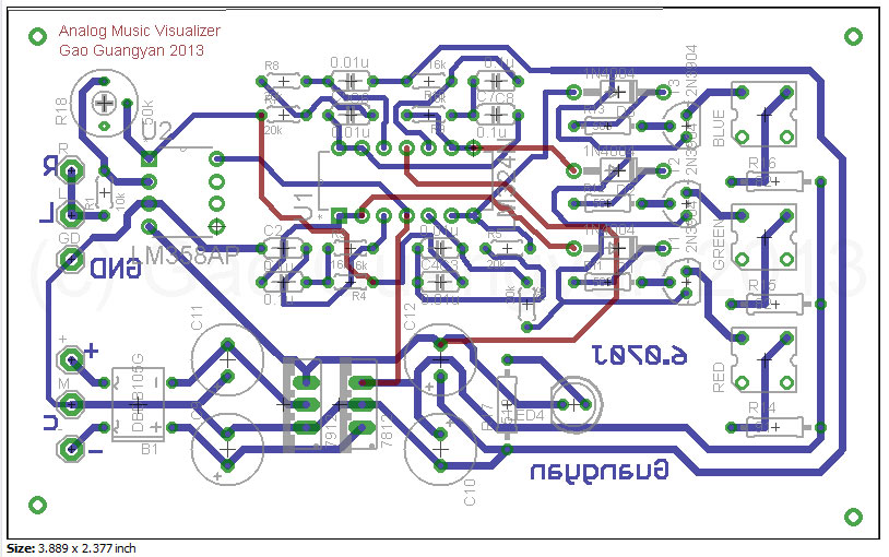
12V rails for the circuit. With the circuit designed, I layed
out the board and etched it.
I couldn't get everything to fit onto one side
so there are some wires which will needed to be soldered in
place (didn't do a double sided etch). Note that there is a
mistake in the labeling of the + and - input (they should be
reversed). The inputs can accept a center-tapped transformer, or
a DC power source with + - and ground.
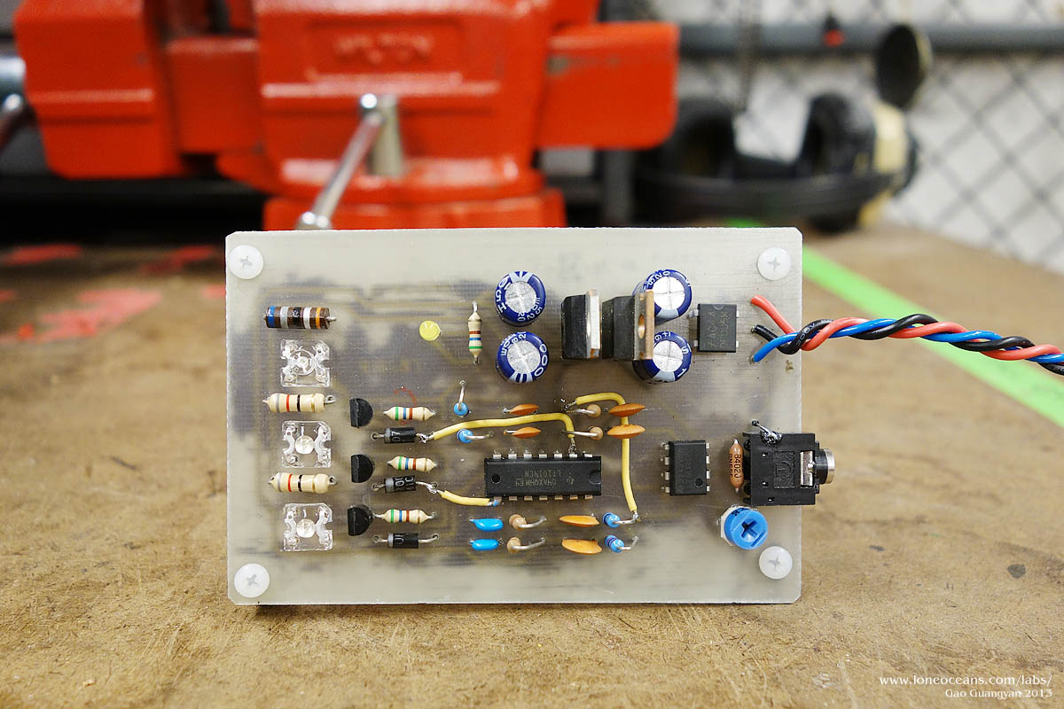
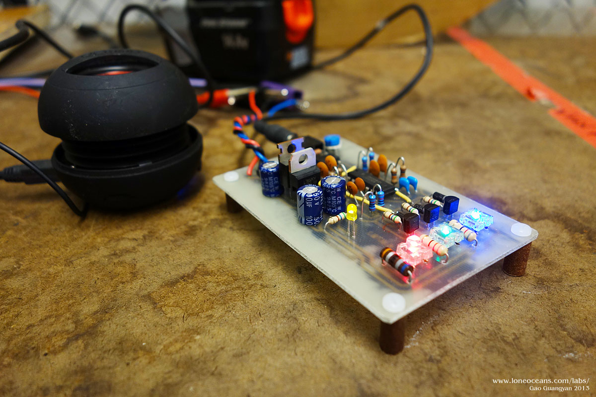
After etching and assembly of the components.
Results - Images and Videos
9 Dec 2013
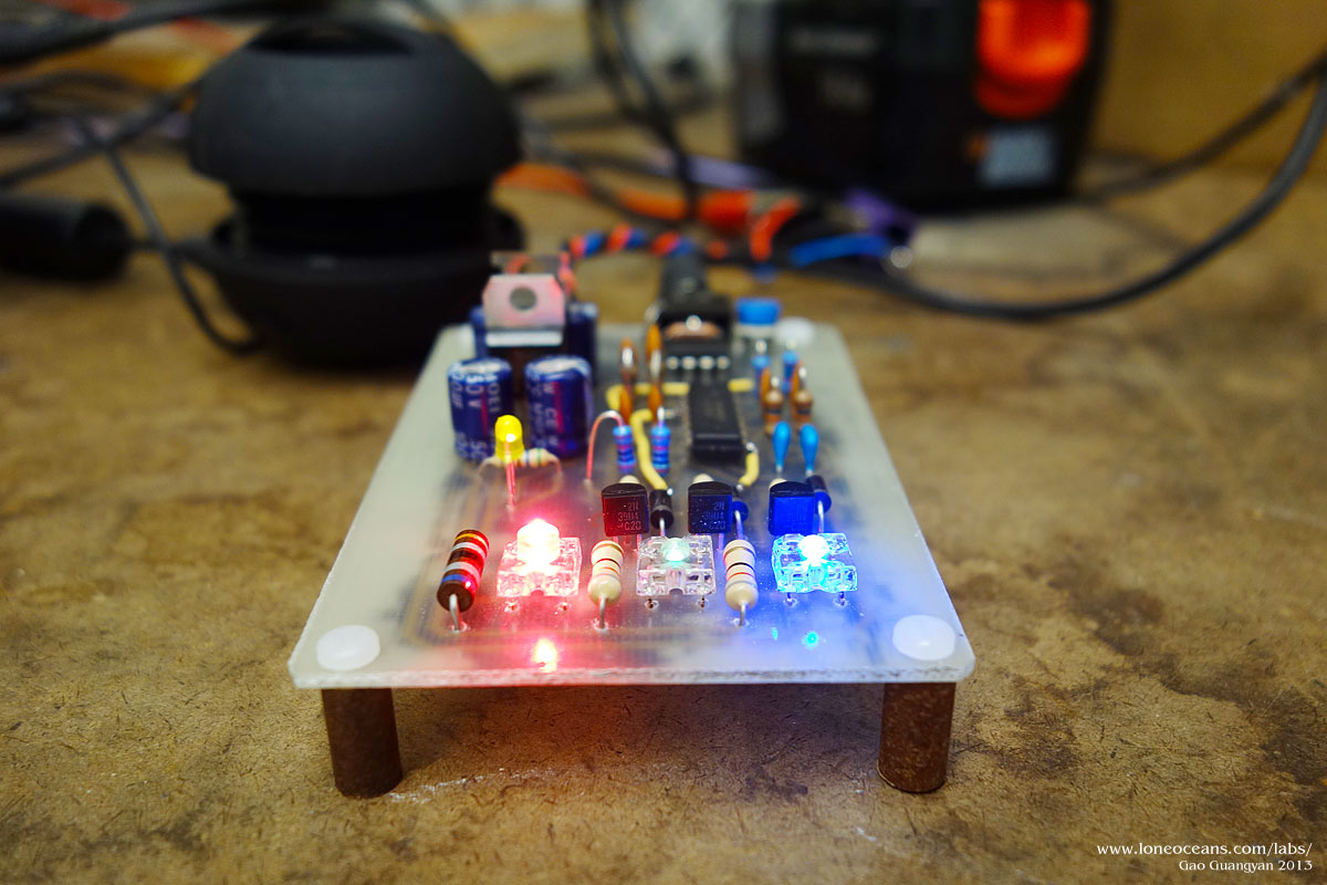
The circuit is done! But will it work?
I plugged it into a computer and did a wave sweep from 20Hz to
2kHz - everything worked out as expected, with a nice sharp
transition between the frequencies!
Above is a video of the circuit in action playing to the tune of
Back Street Boys.
Credits
and Links
These links were helpful in designing the musical
visualizer:
This project was done as part of a introductory
electronics lab class with great instruction from Dr. James Bales.
Back to main page
(c) Gao Guangyan 2014
Contact: loneoceans [at] gmail [dot] com
Loneoceans Laboratories. Copyright (c) 2003 - 2014 Gao Guangyan, All
Rights Reserved. Design 3.
Removal of any material from this site without permission is strictly
prohibited and will result in infringement of copyright laws.
Disclaimer: Projects and experiments listed here are dangerous and should
not be attempted.
www.loneoceans.com/labs/
... page generated in 0.00011 seconds