Twin Tesla Coils
900W, 3", 2006.
17 Oct 2006
Introduction
It's a new year 2006 and this year has been really busy so no real time to do any projects at all.. until now! Now as Vice-Chair of electronics club, I got together with my Chairman and we started discussing what direction to go next for the electronics club, and how to make it more enjoyable and exciting for our members. Hence we decided to start on some hands on activities and finally settled on several club projects. The robotics division was to work on some Omni-directional robot, the Electronics Club worked on a Theremin, and for the Physics division, we decided to build a Tesla Coil. Not one, actually, but a twin system!
So riding on the success of my 180(225)W 40mm Tesla Coil, and the large 3.2kW 4" Tesla Coil 2, I worked with the members and came up with a simple design.
This time, a moderate twin Spark Gap Tesla Coil system, each running at 900W for a combined power input of 1800W, powered by four 15kV 30mA Neon Sign Transformers (two each). Both will run on 3" Secondary coilforms and hopefully put out some serious sparking action! This page will document (non academically) the process of construction of the new Twin Tesla coil system, with construction information, pictures, diagrams and etc. Of course it won't be as powerful as my 3.2kW coil, but with a more efficient design, spark performance might match that and hopefully improve upon my previous coils! Hopefully through a combined club effort, we will come up with something awesome. :-)
Estimated completion date: By Mid November. So stay tuned!
Current Project Status:
Project Completed and Telsa Coils Working! Jan 2007
Just Started 17th Oct 2006
Construction Index
Tuesday, 17th October 2006
Initially planned for the middle of this year, an onslaught of activities from school (as well as the dreaded examinations) prevented the Electronics club from starting on the project quickly. But with the exams over (albeit with school coming to a close), work began on the Tesla Coil. But before you can build anything, you need the materials first. So today I went on a shopping spree for components. After school at 2pm I immediately rushed to the shops and bought my materials. At this point it would be a good idea for me to provide a summary of the entire design of the Tesla Coil. Design had been mostly done already (no doubt helped by the construction of my previous coil), but anyway, here's the design.
Power Supply
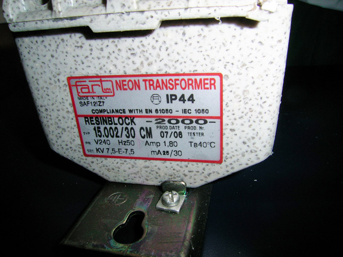
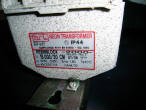
I believe the Power Supply is the most important part of the system because it determines the entire dimensions and characteristics of the resultant coil. With money not being an issue as it was a school sponsored project (we still had limited funds, though), I decided to go for the largest scale we could practically build. Clearly experiments with the 3200W Tesla Coil 2 showed that although extremely potent, the current draw was next to insane and frequently tripped breakers before I installed the soft-start relay mechanism. Safety is of primary concern to the school so tripping breakers was a 'bad thing' to them. Since I've had a small bit of success with Neon Sign Transformers, I decided to go with the much talked about 15kV Neon Sign Transformer. These NSTs are usually not too cheap (well more expensive than used microwave ovens...) so I never did work with them much in the past, but I decided to make each coil powered by a 15kV 60mA 900W power source. Two of them makes 1800W, which is pretty impressive. Problem with the funding is that I can't buy anything which doesn't have a receipt, so even though I could easily get old transformers for about $30, I had to spend about $110 for each 15kV 30mA NST. They will be wired in parallel producing two 15kV 60mA power supplies. Hopefully, they work. So 30kg of metal, and I had to lug it all the way back. The idea with 15kV is that you get a lot of voltage to start off with! This means.. I need some High Voltage wire too.
Capacitor Bank
After some calculation, a 15kV 60mA power supply running at 50hz would require a resonant capacitor bank at 12.7nF. Of course as usual, we want a Larger than Resonant Capacitor bank, hence 12.7 x 1.5 and we get 19.1nF. I decided to go with MMCs using the same RS 1500V 100nF Axial Polypropylene capacitors I used in the 3kW Tesla Coil, so after some estimation, I decided to build a 21kV Capacitor bank. 14 Caps in series with two of these in parallel, making a 28 capacitor bank rated 21kV 14.3nF capacitor bank. Granted not too much over Resonant, but I think it'll work out. Reason? My Tesla Coil 2 ran on a 3200W 8600V power supply. The 41.7nF capacitor bank is clearly under rated because the ideal resonant bank is about 130+nF! But it still performs great! In fact I think it might work even better if I reconfigured the 60 capacitor bank to be 7 strings of 9 (add 3 more) to be a 13.5kV 77.8nF bank. But that's not part of this project, so... but anyway it should work! All bought at about $3.60 per capacitor. That's about $215 but I can't really remember.
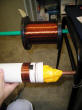
Secondary Coilform
We wanted something respectable yet not too bulky, so I settled for a 3" PVC pipe as the secondary. 60cm of it wound with about 48cm of wire, that should give 960 turns of 0.5mm wire with a 1:6 winding ratio. Respectable. Hence the twins can either be known as the 3" Twins or the 80mm twins.
Sparkgap
The cost and effort of building either an ARSG or a SRSG is quite beyond the time and funds for this project considering school is ending so soon, so it was decided that the best option would be to create a multi-gap static spark gap, effective as proven in my small tesla coil and by many other tesla coil builders. This was made from thick 1" copper pipe and will be adjustable via a brass bolt. We might have a fan blowing some air on it to cool it and to help in quenching.
Total cost so far is about $747.
Wednesday, 18th October 2006
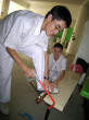  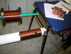
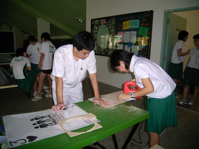
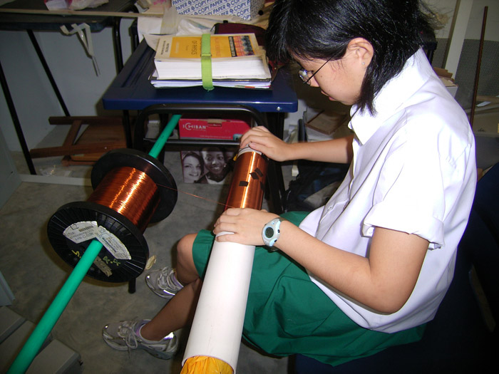
Construction begins! We got our members to start working on the Tesla coil. First up was the construction of the secondary coil and the copper pipe to make the spark gap. The secondary coil must be would immaculately otherwise there would be problems with arc-over and etc, hence before construction I had a briefing about the components before work started. The pipe was sawn to suitable lengths and holes drilled into them. Winding started and members took turns to wind. Unfortunately 1.5hrs passed fast and we had to pack up at 3 for a lecture, but at least work's started! I might go home and clean up the edges of the copper pipe.
Wednesday, 25th October 2006
Construction continues on the second day of proper construction.
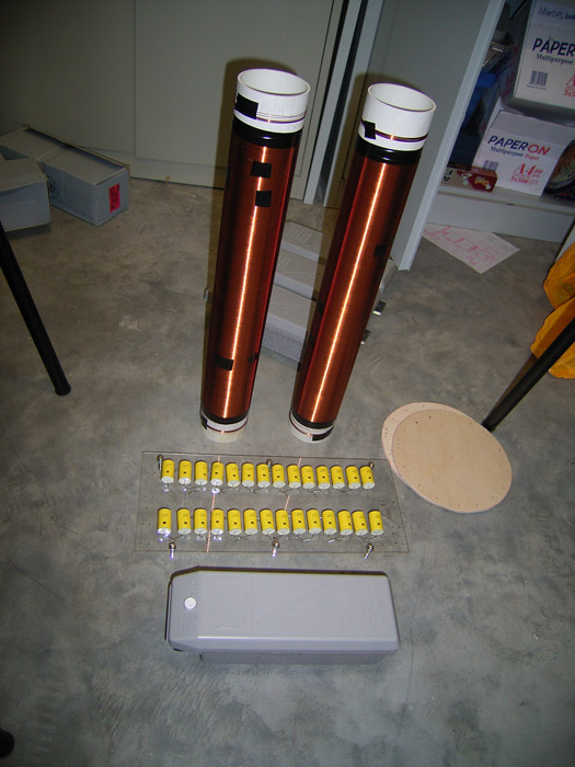
Unfortunately I haven't got much materials to work with so the main aim of the day was the complete winding the two 980 turn coils (that's a total of 492.6m of copper wire, or 861g of wire, so the school now owes me $8.61 worth of wire!) We also cut out circular disks 9 inches in diameter as the main support for the toroids, using the new 400W Jigsaw which Electronics club recently acquired.
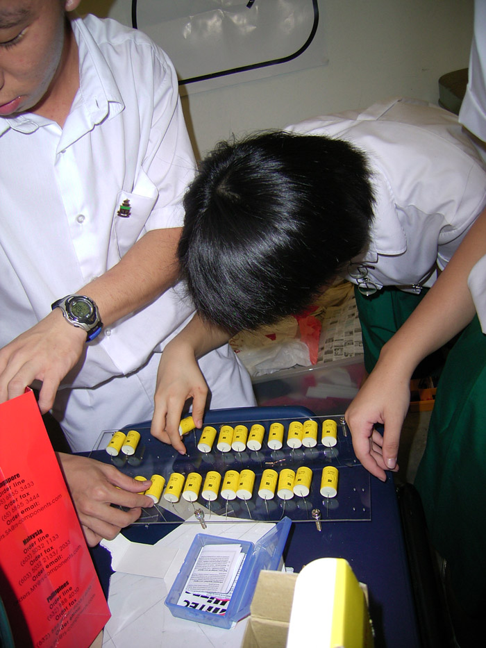
My first small tesla coil ran off half of a 15kV 30mA transformer, running at 225W before the transformer die. I've since replaced it was a 6kV unit. But this time round, we're putting the full 15kV to power the new tesla coils. Since we're running two in parallel, that'll give us 15kV at 60mA. We also got started working on the capacitor bank, as the second coil was being wound slowly by hand.
  
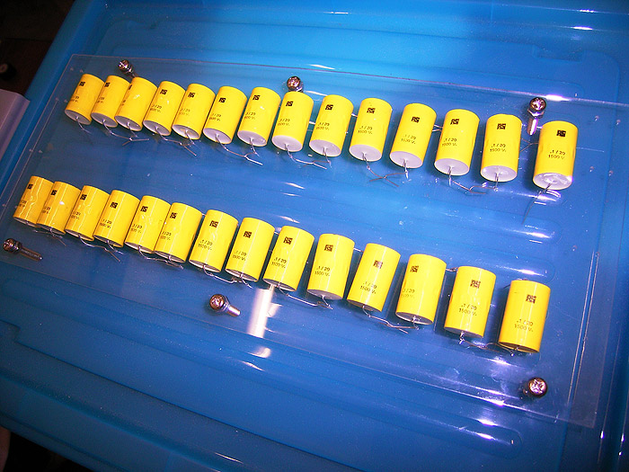
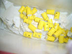
The main capacitor board was cut from acrylic and 28 capacitor were placed in and wired together, making a 21kVDC 14.28nF capacitor bank. And the completed products for the day!
Back to main page
(c) Gao Guangyan 2011
Contact: loneoceans [at] gmail [dot] com |