loneoceans labs | EasyBridge Circuit Board V1.0 (temporary placeholder page)
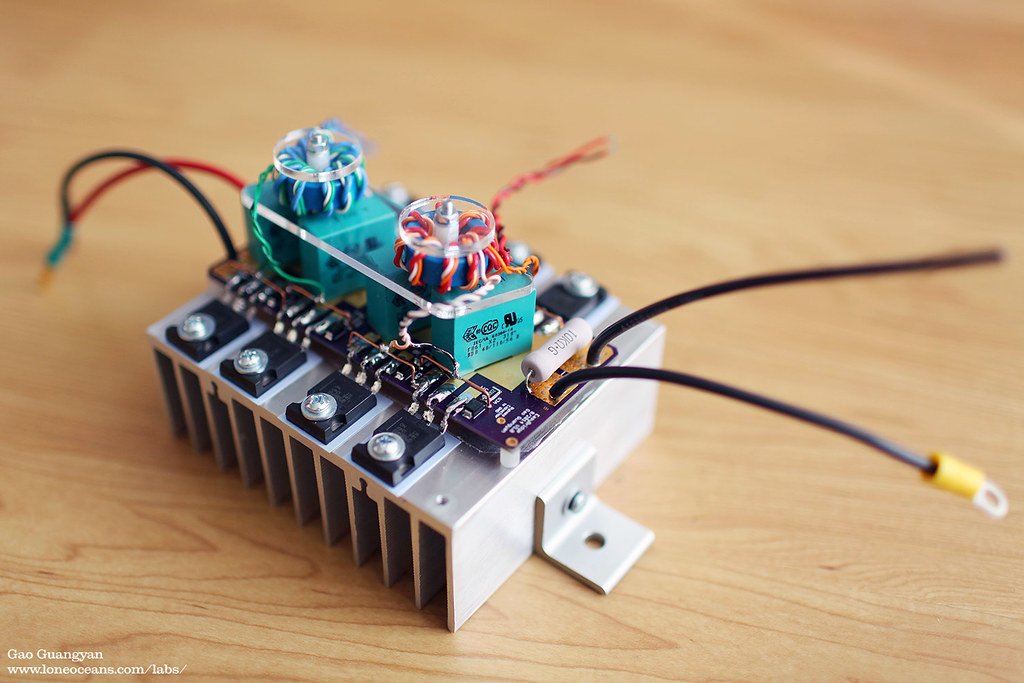
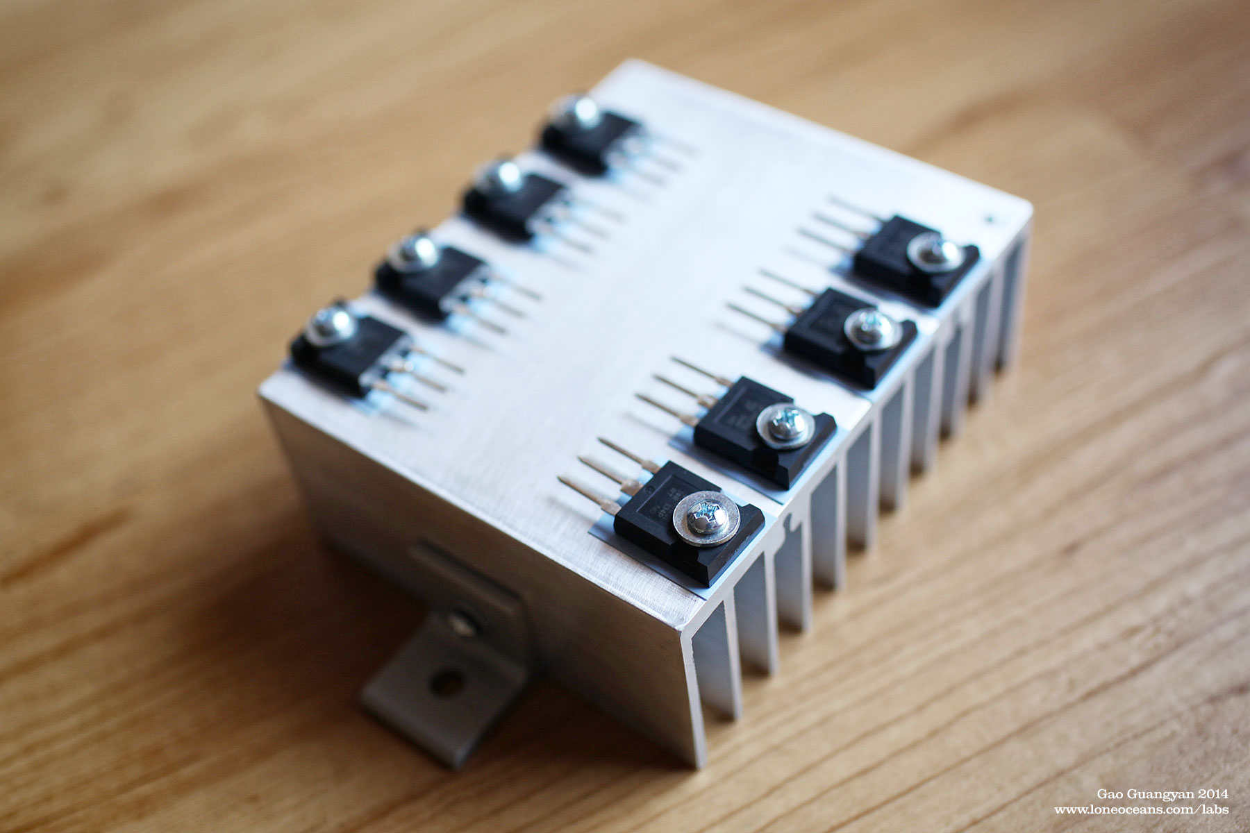
The EasyBridge board in action mounted on a heatsink with 8 TO-247 transistors and two gate drive transformers.
The EasyBridge is an easy-to-use dual-H-bridge inverter system which I designed when building my QCW Tesla Coil. I originally designed the EasyBridge system as a tidy way to build paralleled H-bridges using TO-247 transistors. It is of a compact design and has the main feature of having large pads instead of through-holes for soldering the legs of TO-247 packages.
This allows not only for easy installation, but also for easy swapping out of transistors during a failure (which can happen especially during Tesla Coil usage), and is much easier than standard through-hole designs. EasyBridge also features a layout which keeps paralleled transistors of each leg of the H-bridge as identical as possible to aid in current sharing. The EasyBridge has been tried and tested in my own QCW 1.5 coil running at over 200Apk with no problems, as well as in other hobbyist's coils around the world.
![]() The
EasyBridge system including design, schematics and layout are available above
under the Creative
Commons License.
The
EasyBridge system including design, schematics and layout are available above
under the Creative
Commons License.
What does this board do?
This board is designed for use with all kinds of Solid-state Tesla Coils, such as regular SSTCs, DRSSTCs and QCW DRSSTCs. It can also be used for any sort of H-bridge inverter application, and works with both GDT symmetric gate drive systems such as those used in SSTCs, as well as with external discrete drivers. The EasyBridge accepts a total of eight TO-247 transistors arranged in a dual-parallel fashion, and includes essential features such as 4 decoupling capacitors, MMC discharge resistor, bus bypass capacitor and basic gate drive resistors and diodes. Keep in mind that this board was designed specifically for use in small QCW DRSSTC systems and may not be optimal for different use cases.
The result is very compact, low-cost. simple and reliable double-transistor bridge board.
Please note that if you are building a DRSSTC or a regular SSTC, the 80mm Full Bridge Plus system is much better suited for that purpose with an optimally designed low inductance bus layout and superior power handling capability. However, it only accepts a single Full Bridge instead of what the EasyBridge offers.
EasyBridge V1.1 has the following features
Version 1.1, as of 10/2014.
These boards are currently being offered as a blank PCB for your own customization. These boards are extremely compact and measure only 12 x 5cm.
If the boards are sold out, please check this page periodically. I'll be updating this page if there is more in stock. This board was designed as a personal project and may not work with your set-up. Please note this board was designed solely as a personal hobby board, and interfaces with deadly mains / line voltages! I make no claims that the board satisfies any UL, CE or any electrical standards. You will bear all responsibility for using this board correctly and safely in your project with good engineering practices.
Shipping is from the USA to anywhere around the world (not included but usually relatively cheap) starting at $3.50 for regular mail, $8 for USPS Priority Flat Rate and starting at ~$15 for international orders (subject to change based on shipping rates). All prices are in USD.
Contact loneoceans [at] g mail [dot] com for enquiries.
Schematic
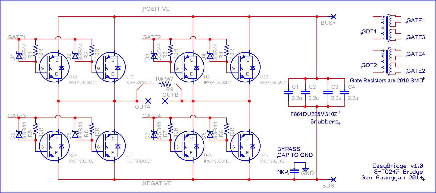
Schematic for the EasyBridge v1.0 is above for reference.
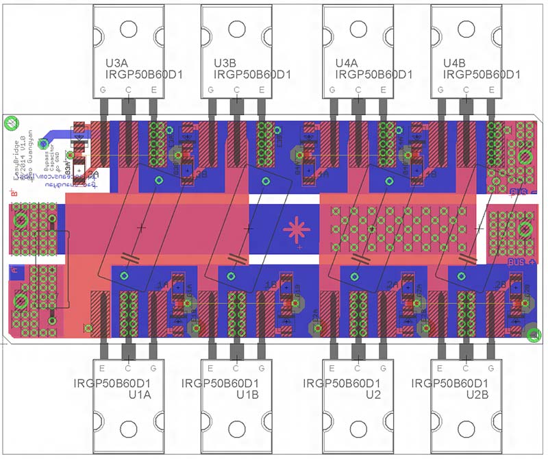
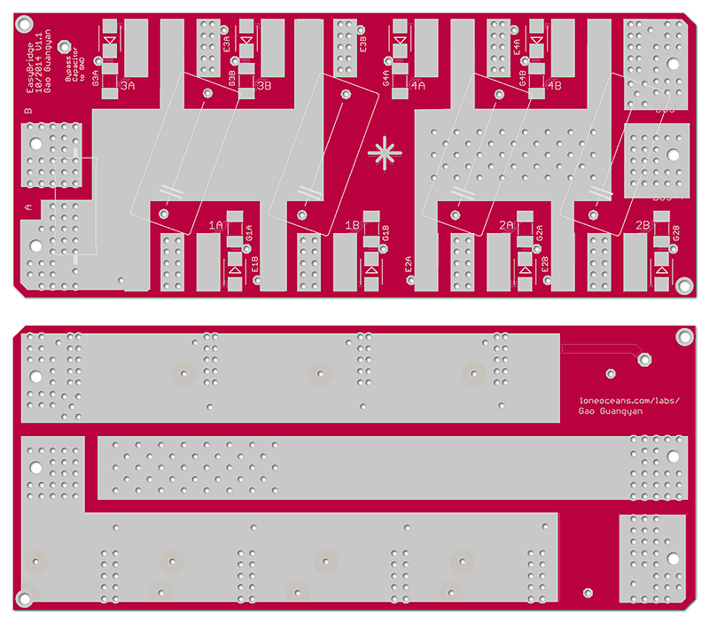
Layout for the EasyBridge v1.0 is above for reference.
Component List
These are the recommended components required for using with EasyBridge. Components are avaliable on Digikey or Mouser or similar.
Main Board Components
- U1A,1B,...U4B - Your favourite TO-247 IGBTs or MOSFETs x 8
Recommended options include FGA60N65SMD, FGH60N60SMD, IRGP50B60D1
- D1 - D8 - Schottky Diode - SSB44-E3/52T x 8
- R1 - R8 - Gate Resistors - 5 to 20 ohms - 2010 size x 8
- R9 - MMC Discharge Resistor - 10kR 6.5W CW00510K00JE73 x 1
- C1 - C4 - Decoupling Capacitors - 26 x 13mm 22.5 LS 310VAC 2.2uF PP Film -
F861DU225M310Z x 4 (or similar)
Other Components
- Bypass Cap to Ground - any good MKP capacitor. E.g. you
can use the same capacitor as C1/C4. Tie other end to GND
- Gate Drive Transformer - wind your own depending on operating frequency.
I recommend Epcos N30 material ferrite cores
- Heatsink - Buy a 120 x 100mm heatsink of your choice online, e.g. search
on eBay for various options
- TO-247 Silpads (also avaliable on eBay for cheap)
Note that connecting wires are required to connect the Gates and Emitters of
parallel transistors together.
Assembly of the EasyBridge
The EasyBridge is designed to work with 8 TO-247 transistors, but you can also use it with 4. These transistors were designed to go onto a commonly available 120 x 100mm heatsink which you will have to drill and tap yourself. Note that isolating sil-pads must be used since most TO-247 transistors do not have an isolated pad.

In order to mount the transistors you will need to bend the legs of the transistors up 90 deg, then back down 90 deg to the pads before soldering. Alternatively, it is also possible for you to use separate heat-sinks to allow direct soldering of the leads without bending.
Please follow the following diagram below for wiring instructions. Note the placement of R9, the 10kR MMC discharge resistor. This resistor discharges the MMC through the Primary Coil after each pulse, aiding the startup for the next cycle. This is a good component to have when operating the bridge in conjunction with a self-oscillating SSTC driver such as the UD2.7. This resistor may be left out when using the inverter for other purposes.
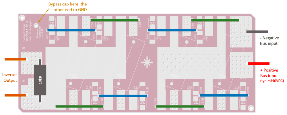
Power in and out can be soldered either directly to the exposed pads, or through the large via. AWG 12 stranded wire or thinner should fit just fine. Note the placement of the large resistor for MMC discharging, as well as the extra via for a bypass capacitor of which the other end should go to GND. This bypass cap helps protect the transistors during a primary strike event, allowing a low impedance path for the arc to discharge to GND instead of through the transistors. Again this capacitor can be omitted if the bridge is not used in a Tesla Coil.
Note the green and blue wires - these need to be connected externally via wires. Please see the photos above to see how I implemented this in real life. The maximum bus voltage is limited by your transistors as well as decoupling capacitors.
===
For more enquires, please contact me at loneoceans [at] gmail [dot] com.
Back to loneoceans labs. (Updated Aug 2018)