Part II - Improvements to my small QCW
1.75m+ Sparks, 400kHz,
5.5" Secondary
|
QCW Tesla Coil version 1.5
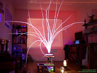 "The QCW, or Quasi-Continuous-Wave DRSSTC is a variant of the Double
Resonant Solid State Tesla Coil and is characterized by its ability to
make extremely long, straight sparks. In 2013, I started building my first QCW DRSSTC (QCW 1.0
- see this page where I have documented in more detail the theory of operation, as well as its
construction progress). I successfully demonstrated proper QCW operation
and achieved a >1m long spark achieving the goal for the project. "The QCW, or Quasi-Continuous-Wave DRSSTC is a variant of the Double
Resonant Solid State Tesla Coil and is characterized by its ability to
make extremely long, straight sparks. In 2013, I started building my first QCW DRSSTC (QCW 1.0
- see this page where I have documented in more detail the theory of operation, as well as its
construction progress). I successfully demonstrated proper QCW operation
and achieved a >1m long spark achieving the goal for the project.
Throughout the course of building my original QCW, I learned
many things and had several new
ideas which I wanted to implement. I also wanted to improve the performance
of the QCW coil. This formed the motivation for this project - QCW
1.5. Therefore this page will be a continuation of the QCW 1.0 page, so
do
check out the original page if you haven't already! :-)
Being perhaps the first comprehensively documented build of a QCW coil
on the internet at time of writing, my original
QCW 1 project page turned out to be extremely
popular, and I've been contacted by numerous hobbyists on questions and
comments, and have received several messages from people who have
successfully replicated the project! So here's a shout-out to all my
readers for your support, and I am glad this website has been a useful
resource.
As part of this project, I developed a few boards such as the
EasyBridge and the
BrickDriver. For those
interested, I have them available if you'd like to incorporate them in
your project!
For this continuation of my QCW 1 project, I have set a few new goals to
improve the performance of the original version 1.0 QCW. This project
will also likely be the basis for a possible future QCW 2. This page
will be a little be haphazard as I conduct different experiments and
test to figure out what works and what doesn't.
The Goal of QCW 1.5 is to achieve a 10x spark to secondary coil ratio at
a driving current of below 200A.
Project Status -
Complete! The goal has been
reached with a spark : secondary ratio of almost 13:1 at <160A
(70"+ spark length!) - June 2015
Thanks for
visiting my page! If you have any questions, wish to share your
projects, or feel that my projects have inspired you in one way or
another, feel free to email me at loneoceans[at]gmail(dot)com. I'd love
to hear about your projects too. :-)
Page Contents
1. QCW 1.5 Planning
and Goals
2. Constructing the QCW (DRSSTC)
3. Constructing the QCW (Bus Modulator)
4. A box for the QCW
5. Results of QCW 1.5
6. Credits and Links
Current Specifications for QCW 1.5 (June 2015)
Changes from QCW 1.0 have been italicized
-
IRGP50B60PD1 Dual Full Bridge Inverter with 'easyBridge v1.0'
- 12.8nF Mica 6kV 40Arms Resonant Capacitor
- 300A 1200V IGBT + Diode in Asynchronous
Buck Configuration with
BrickDriver Gate driver
- ATtiny45/85 for ramp generation and interrupter control with new
integrated buck driver
- 160Apk Primary Current
- UD 2.7C, My own modification of the UD2 driver
- Secondary coil 3.5" x 5.55" 32 AWG Secondary
- New 'FAT TOROID' Geometry: 11.25 x 3.4" Toroid with 5.25"
12 AWG Cylindrical Primary
- 340kHz unloaded secondary frequency
- Run from 240VAC input
- New Bluetooth wireless control capability
- Up to 20+ms ramp time to ~320V
- Large bus capacitance = 10,000uF
Project Goal:
Implement new features and ideas
Performance Goal (Feb 2015): 10x secondary length
Results (June 2015): Just over 70 inch spark
length with 5.55" secondary coil!
For much more videos and images of the coil in action, please scroll down to
Results!
Feb 2015
1. QCW 1.5 Planning & Goals
The newest frontier of Tesla Coils in the modern age is
the QCW DRSSTC, capable of generating huge, long sparks with some clever
drive techniques. Since this is a continuation page, please read my
QCW 1 project page to learn more about QCW
operation. In this section, I will focus the main changes I have planned
for QCW 1.5.
Overall Project Goals
Building on the success of the original QCW design, I
wanted to push it a little bit further and try out some new things as an
experiment for future projects.
Project Goals
- Produce sparks 10x the secondary coil length
- Experiment with new geometries - different secondary, primary coils
and toroids
- Show reliable operation
- Planned running BPS of 0.5Hz to 5Hz
- Operate at 300V ramp
- Be reasonably compact + Build a case for the coil
- Try out some tuning tricks
- Test new ideas I had since building QCW 1.0
The QCW Tesla Coil can be broken down into three main parts - the
buck converter, the DRSSTC, and the ramp generator. Let us look at these parts separately in more detail. Note that this section contains my
initial plans (end 2014/early 2015) and final specifications might change as the build
progresses.
Buck Converter
QCW 1.5 will retain basically the same bang-bang
feedback controller I
developed for QCW 1. However, I was never really happy with the
implementation of the power electronics. Instead of using two TO247 IGBTs and separate diode, I
decided to give a new general purpose brick-IGBT driver I designed earlier on last year
a try, and use a large half-bridge IGBT module for the main switch instead. A
half bridge module is particularly suited for this task because it
contains two IGBTs with reverse diodes in a single low-inductance
package. This also means less wiring on my side.

IGBT modules come in various configurations in the same industry
packages - images from Semikron's product page
The idea was to use the upper IGBT as the main
asynchronous buck switch, and the bottom IGBT forced open, using only
the reverse diode as the main buck diode. This is a bit wasteful, and in
real life, one can buy IGBT modules with only an IGBT and single
Diode (in upper and lower switch configurations) for cheaper than a new
dual-switch. But I did have a bunch of half bridge surplus modules lying
around, so my choice was driven simply with what I had on hand.

62mm Infineon IGBT module - photo from Infineon's
product page
I will be using the
Infineon FF300R12KS4 IGBT, which is good for 300A at 1200V -
again no particular reason for the choice, just that I had one spare lying
around. I note that I am actually finally using the IGBTs as they were
designed for (instead of in DRSSTC use!)
This IGBT uses Infineon's own NPT IGBT2 chips
for high frequency switching (S series Fast Short-tail IGBT chip),
similar to the Semikron 125D line, with a square RBSOA good to 600A at
the low voltage (<400V) we are running at, and has supposedly 'unbeatable
robustness'. The driver will be my custom
IGBT brick driver which I developed a while back, with desaturation detection and good for up to 600A+ IGBTs.
Because this is a bang-bang controller, switching frequency will vary
depending on the feedback parameters and I'll be adjusting it to be around ~5 to 30kHz, comfortably within the IGBT's datasheet capabilities.
In the version 1 QCW coil, I had quite a bit of problems keeping up with
the long pulse with my small 3400uF bus capacitor, so the capacitor will be
upgraded to a single 400V 10,000uF bus capacitor, charged up to 340V from
240VAC rectified, with a ramp peak at around ~300V. This should be an
improvement over my 1.0 QCW which made ~1 to 1.2m sparks with a 150V
ramp before the capacitor voltage dropped too low. In the future I might
have to either use a buck boost topology or a higher voltage bus
capacitor to better make use of the energy stored in the capacitor.
DRSSTC
The DRSSTC portion for QCW 1 performed admirably, but
there were several things I wanted to change / experiment with. There
were two main experiments I wanted to try. Below is an outline of my
plans. Go on to the results section to read about the results :-).
 Experiment
1 - Operating Frequency (April 2015) Experiment
1 - Operating Frequency (April 2015)
Due to an oversight on my part when calculating the
resonant frequency for the version 1.0, I wound up with a base resonant
frequency of 400kHz, which at upper pole operation, resulted in an
actual QCW 1 upper pole operation frequency of 460+kHz. This is
beneficial for sending power into the secondary, but stresses the main
IGBT bridge more due to the high switch frequency. I was also at turn
7.5 out of ~12 turns on my primary, so I knew I could drop the frequency
significantly to reduce IGBT switching losses and have lots of tuning
space to spare on the primary.
Experimentally it seems that for straight-spark growth,
a frequency of 300kHz or higher is required. Therefore I decided to make
a new 3.5" x 6" secondary coil wound with about 840 turns of AWG 34 wire
with wire insulation taken into account. With the same parameters for
the rest of the coil, this should drop the new resonant frequency to
290kHz, putting the upper pole somewhere around 350kHz.
Results (May 2015) - New secondary coil and
8 x 2" toroid operated around 300kHz. Together with the conical primary at
~turn 10, the system resonated at the upper pole of 360khz with a
coupling of 0.308k, and operating frequency dropped to 340kHz with a
~200V ramp at around 150Apk. Ramps of 10ms consumed about 78J per burst,
with a longer 15ms ramp producing significantly straighter sparks. Spark
length achieved was about 1.2m. It seems that spark de-tuning is
significant and causing excessive primary current and therefore less
efficient power transfer. Experiment 2 will instead focus on a new design with a
larger toroid and higher coupling.
Experiment 2 - Coupling and Secondary Capacitance
(May 2015)
 This experiment was motivated after
insight gained from
the first experiment. It seems that spark-loading is detuning the
secondary coil leading to less than ideal power transfer, so the idea is
to try to reduce this de-tuning effect by doing two things: This experiment was motivated after
insight gained from
the first experiment. It seems that spark-loading is detuning the
secondary coil leading to less than ideal power transfer, so the idea is
to try to reduce this de-tuning effect by doing two things:
1. Increasing coupling
2. Increasing topload capacitance
The game plan is to improve impedance match between
the driver and the spark to more effectively send power into
the spark as it grows. My original conical primary coil had a
coupling of around 0.3k, and I wanted to increase this to closer to 0.4k
Hence I designed a new cylindrical primary coil. The idea is that
while this will shift the upper pole higher away from the secondary
frequency, the overall detuning after spark loading will be
proportionally less. To maintain a good operating frequency, I will revert back to the original
green secondary coil but add a new larger toroid made of 3" ducting, for a
new f_sec around 340khz. This experiment will be conducted with
the primary set to as low as possible while still kicking the coil into
the upper pole, and current limit to be set around 160A.
Results (June 2015) - Experiment 2
turned out to be excellent, resulting in exactly the impedance matching I was
looking for. The results are obvious. With the secondary coil around
340kHz and a coupling of around 0.38, the coil self-oscillates around
413kHz and drops to about 376kHz or so (depending on the actual spark), with a
measured
spark length just over 70". Maximum ramp is just over 300V before my bus
cap (charged to ~380+V) drops too low. At the peak of the ramp, primary
current hovers between about 145 to 160A. Total pulse length for a good
spark growth is about 22ms with the rising ramp about 16.5ms rising up
from ~75V. Pulse energy is just around 275J. At this point, the project
has exceeded its goals!
Measurement (27th June) - Bus cap charged till 397V,
dropped to 326V after one pulse (256J). Primary current ranges from 148
to 165Apk. Current initially ramps up to about 75A in the first 640us
(with a 75V bus). Once the coil begins running (the 'wick' phase), bus
voltage drops to around 50V (60A primary current) before ramping up to
just around 300V. Buck switching frequency begins around 13.6kHz going
up to a maximum of around 29.7kHz, and then to 19kHz at the peak of the
ramp. Total wick duration lasts for about 1500-640us. Peak reached
around 17.7ms, and ramping down to 25V at 22.5ms. Turning off the coil
results in a small voltage jump to 80V before it decays down.
The bridge will continue to be the same bridge made of
the fantastic Warp2 IGBTs from IR, but this time I thought I'd re-wind
the GDT to use a single large GDT core, with a +-24V IGBT gate drive
from my UD2.7.
Ramp Generator
The ramp generator will be exactly the same. To simplify
things a bit, I decided to put the microcontroller on the tesla-coil
side, and this the user will be able to control the pulses sent to the
coil instead. I also added Bluetooth capability so the coil can be
controlled via a smartphone, but this is more of a gimmick than anything,
if it actually even works
:-). Otherwise fiber-optic is still the way to go.
With the main plans set, it is time to work on the
build.
2. Constructing QCW 1.5 - The DRSSTC
April 2015
New 34 AWG Secondary Coil (eventually not used)
The secondary circuit in QCW 1.0 resonated closer to 390kHz, and
in upper pole mode operated closer to 465kHz. For the
first experiment, I wanted to try with a lower frequency secondary
coil, so I made a new secondary coil with the same 3" PVC pipe
(3.5" outer diameter), with red AWG 34 wire. This has a
nominal thickness of 6.3
mil, but with wire insulation should bring the actual diameter
to ~7.3mil. For a 6" winding length and a 99% fill, this would
give me about 822 turns. I managed to wind the coil on the lathe
with automatic feed,
which despite the thin 34 AWG wire, went quickly in just 20
minutes. The final actual winding length measured around 6.3".
End caps were made from acrylic, with holes drilled and tapped
to accept 6-32 nylon screws for attaching it to the pipe.

The coil was then given 3 good layers of Minwax clear gloss
polyurethane, which is my favourite varnish for finishing coils.
Next was finding the actual resonant frequencies to characterize
the system properly.
Secondary standing alone on a cardboard box with 8 x
2" toroid - 302.7kHz
Secondary standing alone with toroid and wire (simulated
streamer) - 228.3kHz with 1.0m wire, and 209.8kHz with 1.5m wire to
table
Primary alone on a cardboard box with no secondary - 321kHz @ 9.5,
306kHz @ 10, 291kHz @ 10.5.
Primary + Sec (grounded), Turn 10, primary
frequencies - 255, 362kHz (lower pole, upper pole) (282/394kHz
ungrounded secondary), k = 0.306
Primary + Sec (grounded), Turn 10.5, primary frequencies - 252.5, 352kHz
(lower pole, upper pole) (275/391kHz ungrounded secondary)
Secondary resistance - ~210 ohms
The coupling of two resonant systems results in an overall
frequency response with two resonant peaks, and can be
calculated based on the geometry of the system via the coupling
coefficient k. At turn 10, the coupling of my system was
calculated to be k=0.306.
f_upper = f_natural / Sqrt (1 - k)
f_lower = f_natural / Sqrt (1 + k)
..where f_natural is the resonant frequencies of the primary and
secondary circuits in isolation. The calculation of different
resonant frequencies is more complex and left as an exercise for
the reader. Using f_natural =
302.7kHz, the calculated poles are 363khz and 265kHz, which are
in reasonable agreement with the measured poles at turn 10 with
a grounded secondary. Overall the new secondary system turned
out exactly as I had planned with a ~300khz operation frequency.
The toroid can actually be lifted up to further drop resonant
frequency (e.g. lifting it up by an inch drops f_sec to 300khz).
The resulting coupling coefficient is lower than I
was hoping (wanted closer to 0.35 to 0.4), but a new primary
should be straightforward to make if required.
New Larger Toroid aka. "FAT
TOROID"

For experiment 2 I wanted to make a new secondary system with a
lower ~340khz frequency but with a larger toroid. For this
system, I went back to my original 32 AWG 5.55" long secondary coil
used in QCW 1.0,
together with a new toroid made out of out of 3" PVC ducting.
The ducting was larger than I had thought and the result is a
3.4 x 11.25" toroid, which looks a bit wonky on the small
secondary coil since it's twice as big as it is! Because of this
I will call these setup the "FAT TOROID" setup.

I also made a new primary coil out of AWG12 wire with a 5.26"
diameter. The coil was tapped around turn 10 for a resonant
frequency around 330kHz. To simplfy construction, I designed the
mounts and laser-cut them in acrylic. Putting everything
together went quite quickly as can be seen above.
Here are the resonant frequencies as measured.
32 AWG Secondary standing alone on a floating wooden plank with new
large toroid - 339.3kHz
Secondary standing alone with toroid and wire (simulated
streamer) - 285.6kHz with 1.0m wire to table
Primary at various frequencies (turn 12.75 - 274kHz measures,
273.9kHz simulated).
9 = 355.5; 9.5 = 341.3; 10 =328.4 (328.9 measured) ; 10.5 =316.46; 11 =305.7;
11.5 =295.7; 12 =286.49; 12.5 =277.9
Can use equation Freq(kHz) ~ 1842.1 x N^(-0.749)
Primary + Sec (grounded), Turn 10, primary frequencies - Upper
pole = 420.2kHz (408.6?)
Coupling k = 0.38
This setup will be used in the 2nd experiment.
Tuning Tricks (future reference)
One new thing I wanted to try was doing some tuning tricks to
improve spark length while using less primary amps. My QCW setup
has a high coupling, and frequency splitting creates two
resonant poles almost 100kHz apart. To improve power transfer
from the primary to the secondary, matching the resonant
frequencies is important. I am using a conventional feedback
driver - in this situation there can be three drive modes:
1. Setting f_pri = f_sec. This can lead to natural
excitation of both pole frequencies, leading to notching in current at
the beat frequency, and is therefore not ideal.
2. Setting f_pri < f_sec. This causes the driver to
oscillate at the lower pole. As the spark grows, the secondary frequency
drops due to spark loading. This causes the system's lower pole to drop
further; the the coil begins out of tune and continues to be more out of
tune - not ideal as well.
3. Setting f_pri > f_sec. This causes the driver to
oscillate at the upper pole. However as the secondary freq drops, the
system's upper pole also drops but now brings the system closer in tune.
This is however still not the most ideal, but is the best of the 3
options.
So Option 3 is the best method for conventional tuning. However,
the coil still goes out of tune and becomes quite inefficient,
resulting in more energy stored in the primary instead of the
secondary circuit. However, a tuning trick allows us to avoid
this. For example, in a conventional upper-pole tuning, Steve's
QCW 1 required about 280A for 6 foot sparks, and maybe 200A for
5 feet. Zrg's QCW also required about 300A to make 6-7 feet
sparks. However with the tuning trick, it is possible to
generate 5 foot sparks with just 110A. Otherwise I'd expect
~150A to be only about to make roughly 4 feet sparks.
The trick is to tune f_pri to lower than f_sec, but drive the
coil at the upper pole. Now what happens is that as f_sec drops,
the operation system frequency drops and and the coil becomes
more and more in tune as the spark grows, allowing power
transfer to the spark. However this cannot be natively done on a
conventional feedback driver; there must be some sort of
starting oscillator to kick the coil into a different pole
operation before feedback over-rides the start-up oscillation.
[ More to come on tuning tricks! ]
Gate Drive Transformer
I thought I'd write some notes on gate drive transformer (GDT)
design. I started off with a toroid core I already have. It is a
MnZn ferrite core B64290L0659X065 by Epcos/TDK made of material
T65 (B_sat of 4600 Gauss at 25C) which is designed for use
broadband transformers with an optimum operation frequency of
10kHz to 200kHz. It has a very high initial permeability of
5200+-30%ui, though perhaps N49 material would be more suitable.
It however has an extremely high inductance factor AL value of
8200+-30% nH (L/nH) and an effective cross section area of
125.3mm^2. The number of turns on the toroid can be calculated
using the following equation:

.. where B is the flux density in Gauss, A_core is in cm^2 and
"ET measures the energy-handling ability of a transformer or
inductor, and depends on core area, core material, number of
turns and the duty cycle of the applied pulse" - (information
from powerelectronics.com).
To prevent the core from saturating, we need to use a minimum
number of turns. We can calculate the flux density B = (V x t) /
(N x Ae). Although B=0.46T, we can be conservative at set
maximum B to be 0.2T. Now V = 24V (we're using a 24V 50% duty
cycle gate drive at say 300khz). This gives us an on time of
1.67x10⁻⁶s. Note that Ae = 1.253x10⁻⁴. Re-arranging, we see that
N = Vt/BA, and the minimum number of turns to avoid saturating
the core is 1.6 turns! So no problem here.
A tradeoff exists to use as few turns as possible without
saturating the core and to minimize the leakage inductance, and
increasing the number of turns to reduce the magnetizing
current. This can be given by I_mag_rms = 0.577 * I_peak = 0.577
* Vp2p * period * duty / L, where L = AL x N^2.
Preliminary Testing of the DRSSTC
With the coil ready to go, I use a small 940uF 400V capacitor as
the bus cap and started testing the DRSSTC to make sure the
driver is working and is tuned to perfect zero current
switching.


I'm using the same 8-TO247 IGBT 'easyBridge', same as the one I
used in QCW 1.0. These use the fantastic Warp2 series IGBTs from
IR. The driver is the usual UD2.7C. Note that addition of a very
large 35V 5600uF capacitor on the 24V rail - this is required
due to the long pulses required for driving the IGBT gates
during QCW operation.


During each QCW pulse, the transistors will be switching several
thousand RF cycles. It is important to keep any switching losses
and switching spikes to a minimum. I carefully tuned the driver
for perfect zero voltage switching. The four scope shots show
the primary current (pink), Vge (yellow) and Vce (cyan). In the
top two, there is insufficient phase lead. The current in this
case is just about 50A, but even with the bus at 100V, we are
seeing spikes (cyan) of almost 100V due to slightly late
switching!
The bottom two photos show the result after phase lead
adjustment. Here the primary current reaches about 110A or so
with 128V on the bus. Despite this, switching is perfect with no
switching spikes. As a result of the clean ZCS switching, there is also a lot
less switching noise and EMI - compare how clean the bottom
trace looks like compared to the top trace. Here the coil is
tuned at 360kHz.
On to the bus modulator!
3. Constructing QCW 1.5 - The Bus Modulator
April 2015
The bus modulator is the heart of the QCW and
what differentiates it from a normal DRSSTC. There are a few
ways of implementing this (see my original
write up), but I am implementing it as a high-current buck converter that feeds a rising voltage
bus into the inverter input. I have used a simple asynchronous buck
converter topology due to its simplcity. As mentioned, the main switch comprises of
an IGBT in a half-bridge 300A module, and the catch diode being the
reverse diode in the other half of the module (with the IGBT not
being used). To drive the main switch, we need a proper gate
driver.
New IGBT brick driver
As a fun engineering exercise, I developed a new
proper general-purpose brick driver for all my brick driving needs. This really
isn't required though. For comparison, my previous
implementation used a FOD3184 for the buck switch's gate driver
which worked just fine. But it's always fun to try to do
something new :-).
My new brick driver is based off an industry standard Avago HCPL-316J / Fairchild FOD8316 opto-isolated IC with fancy features
such as complete integration and opto-isolation, 2.5A gate drive,
de-saturation detection, fault feedback, under-voltage lockout and so on.
This was configured with a push-pull transistor output buffer stage to
boost the gate drive capability to something like 20A capability,
driving the gate with conventional +15 -8V drive voltages. In the event
of a fault, I have configured the driver to automatically reset which
occurs at the next gate drive low signal.

The cool thing is that I've developed this driver to be
as general purpose as possible, and I'm happy to say that it will be
making its debut in this project! I'm sure I will find a lot more uses
for it very soon in future projects. I routed the PCB after designing
the circuit. Notice how it has an array of mounting holes to fit a
variety of IGBTs. The entire assembly was mounted on a heat-sink
together with the main rectifiers.


Above shows an early test (Vge) when
driving the FF300R12KS4 (3200nC gate charge) with R_on of 4.7 and R_off
of 2.0 ohms in addition to an internal 1 ohm R_g, at a 20kHz 50%
duty-cycle. The miller plateau is very obvious around 8V. The resistors
were later reduced in the bus modulator for slightly faster turn on and
turn off speed, but at the cost of higher EMI during switching
transitions.
The buck switch was mounted on a single heatsink with
its own integrated rectifier and 20uF buck output capacitor. Using a single
module simplifies physical construction and reduces circuit inductance.
Care was also taken to minimize inductance on the power rails just as one would do
when constructing any other power circuit.
New Integrated Buck Controller
The bus modulator controller relies on the same
bang-bang feedback control I used in the version 1.0 modulator for
regulation. However it has a few new improvements - added
several adjustment points which allow me to fine-tune hysteresis and
feedback characteristics to increase/decrease switching frequency and
therefore output ripple. It also accepts Bluetooth signal input!

As per my previous implementation, the ramp generator is implemented via
a ATtiny45 microcontroller with control potentiometers to adjust for the
pulse width and ramp height, as well as generating the interrupter ON
signal. This controller now also sits on-board for a more integrated
solution. After writing the firmware for the controller, I programmed
the IC and began testing the new integrated controller. The circuit was
tested on a breadboard first before I routed a PCB for it. The control
board also has a capacitor discharge and gate driver output, which can
be used for switching a FET/IGBT to discharge the buck output capacitor
after each pulse. This can be useful if an OCD event occurred and the
output capacitor remains charged.


Above you can see the output of the ramp signal,
adjustable from 0 to a maximum of around 18+ms going up for 80% of the
time and ramping down for the last 20%. In order to aid start-up, the
ramp generates a step corresponding to around 40V for about 1ms. This
'wick' allows the coil to begin oscillation before the actual ramp,
otherwise the coil would not be able to begin oscillating from 0V on the
bus. From the scope images, note how I can increase the max height of
the ramp while keeping the same gradient, and I can also adjust the
pulse width of the ramp, while keeping the same height. The yellow
signal shows the logic signal to the tesla coil interrupter. It has been
experimentally found that a linear ramp like this works great for spark
growth, but this is no reason why this cannot be an arbitrary signal,
for example an audio signal. In this way, the bus modulator can be used
as a
high power amplifier for musical CW-SSTCs.
One technical issue to note about the bus modulator is
that in the event of a current trip event, the sudden turning off of the
bridge causes the (large) residual current in the buck inductor to have
nowhere to go, creating an over-voltage situation on the bus of the bridge.
If this exceeds the IGBT voltage, it will cause IGBT
failure with horrible results! This is clamped using a high speed high current rectifier back to the bus
caps.

The output of the controller is sent to the brick driver, and buck
output sense wires go back to the controller for feedback. The result is
a modular and compact integrated board which I designed to be the same
footprint as the coil driver, and hence fits easily inside the same shielded
case.
Control to the circuit is done via fiber-optic, but in a
bid to further reduce wires, the board also accepts a bluetooth module
for communication with a bluetooth device such as my smartphone via a
simple application. This allows me to send pulses to the control board.
To avoid any sort of EMI, the board locks out immediately after
receiving the signal providing dead band immunity. For power-cap, I've
also arbitrarily set the maximum possible pulse rate to just about 9Hz
for a roughly 15% max duty cycle.
Problems Encountered (and fixed)
Finally, I encountered some problems on and off with
various components of the feedback circuit. First was mostly due to
feedback noise, likely caused by noise pick-up during the hard-switch
events in the buck. This manifested itself as a high frequency switching
instability fed back into the regulation circuitry. It took me a while
to figure out since simply probing the circuit exacerbated the issue.
The final solution was simple managing my wiring properly, keeping
feedback wire pairs twisted and reducing stray inductance, shielding
everything in a grounded case. I also added a ferrite bead on the V+
feedback (adding one to ground had a very detrimental effect!), and this
solved all my noise issues.
Secondly I messed up the common mode voltage inputs in
my comparator - the TL3016! It turned out that the common mode input
range with a +5V supply was 1.25 to 3.5V, causing the output to be very
unstable at low voltage comparisons! I eventually replaced the part with
a LT1719 device, designed specifically for low voltage operation, from
100mV below V_EE to 1.2V below V_CC. The LT1394 could probably be used
as well. Regardless, this fixed all the issues I had with feedback
resulting in beautiful clean operation (more scope shots below).
Preliminary V1.5 Bus Modulator
Testing
May 2015
After a good bit of on-and-off work, I wired up
version 1.5 of the 'Buckverter' for it's inaugural run. For its
preliminary test, I used a small temporary 900uF 450V capacitor
charged up to around 400VDC as the bus capacitor, with a large 5
ohm resistor as the output load.


After some small adjustments in the feedback of the coil
and some debugging, the circuit worked great! I've arbitrarily adjusted
it so the max switching frequency in this test to be just about 17kHz.
Above you can see the voltage across the load - a ~40V step going up to
a beautiful ramp to about 315V, for a peak current of just over 60A and
a pulse energy of about 30J. The peak was reduced slightly in this case
due to the capacitor voltage dropping too much at the top of the ramp.
With the output inductor of 113uH and a total output
capacitance of 28.8uF, we get a cut-off frequency of around 2.8kHz. The
switching frequency can be adjusted on the fly for better ripple
performance since I had feedback trimmers designed into my buck control
board. For the actual bus capacitor, I managed to acquire a
Hitachi 10,000uF 400V (450V surge) capacitor
which should be a big improvement from my 3150uF bus capacitor I was
previously using in V1.0. The datasheet lists a ripple current handling
capability of 49.4A, 19mOhm ESR and 24nH ESL. This will be used in
actual QCW operation.
With the bus modulator working as expected, it's time to
put it together with the coil!
4. A Box for the Coil
May 2015
My QCW setup was getting quite unwieldy being a
bunch of components and wires all lying about on the floor. So I
decided to make a very simple case for it so I can move it
around easily, and so that it won't collect so much dust when
sitting around.


The box was simply made of some scrap polycarbonate
sheets and aluminium supports, and measures just around 12 x 18 inches,
making it reasonably compact.

For safety, I integrated an on-board LED
voltmeter panel which tells me the voltage of the large bus capacitor. I
could probably have made it even more compact by some stacking of
components but I think the overall result is ok. In the overview, you
can also see the bleeder resistors, as well as a start-up bypass
resistor mounted on a small heatsink if a variac is not used during
start-up.
5. Results - QCW 1.5
23 May 2015
First Light (and Experiment 1)!
After a few weeks of restarting the project, I was able
to put the components together for QCW V1.5's inaugural first light
run. This was done with a new 34 AWG secondary. It all came together and the coil performed very well!
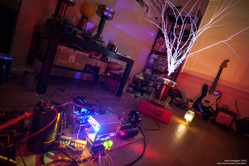
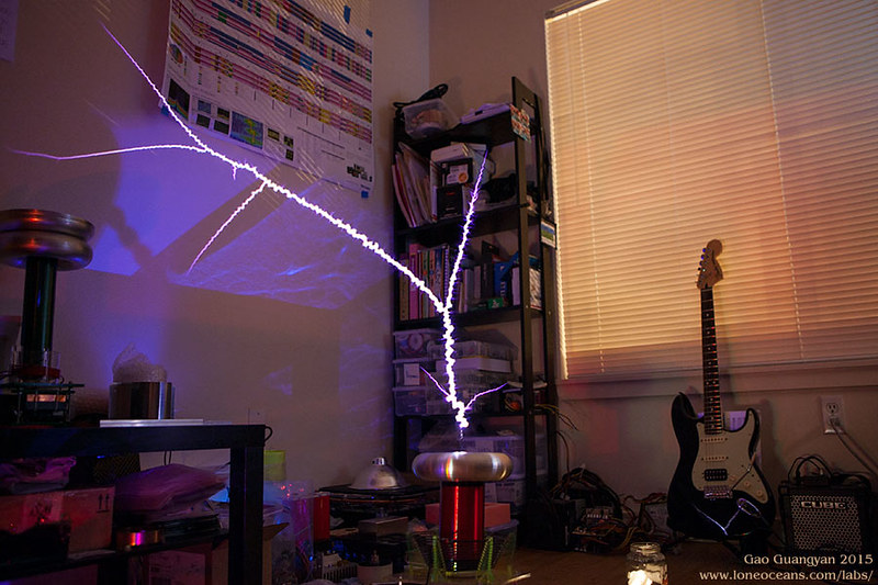
This entire test was controlled by my phone via
bluetooth - this worked a lot better than I had expected, and turned out
to be very convenient! I also managed to catch a trace during this first test.

Blue shows the bus voltage and yellow the primary
current throughout the tramp. At the beginning, there is a small pulse
on the bus to about 50V where the 'wick' begins - here the buck
regulation isn't that great, so it's something I need to continue to work on. Then the interrupter
line is turned ON and the coil begins oscillation. The buck switch
frequency at the beginning is a relatively low 8.5kHz, leading to some
quite large ~30V+ ripple. Correspondingly there is quite severe ripple
in the primary current (starting oscillation 360kHz). As the ramp
increases, the switching frequency increases to 18.9kHz, with a much
smaller ripple of around 20V. At the top of the ramp, the resonant
frequency drops to 340kHz due to spark loading.
Total pulse length is
about 11ms long with a peak of just about 200V. Primary current peaks at
just below 150A, and spark length is about 4 feet (120cm) long with the
bus capacitor charged to just about 350V. Each pulse was measured to
consume about 76J. At this point I've set the OCD to just over 150A as a
bid to run 'within' the 75A pulse ratings per IGBT - turns out that this
was about the maximum ramp I could use before hitting the current limit.
Even so, performance is in line with Steve's 200A for 5 feet and
280/300A for 6+ feet.
28 May 2015
It seems like I was hitting 150A just around a
200V ramp input, so before working on the next experiment, I did
some adjustments to my ramp generator to allow for a lower
voltage but longer ramp. My hypothesis was that there exists a
particular power ramp gradient where a ramp too low would
produce knarly, segmented sparks, while a ramp too long would
produce a really hot and fat but bushy spark. The idea is to
ramp it just enough for it to grow long and straight to produce
the longest sparks.
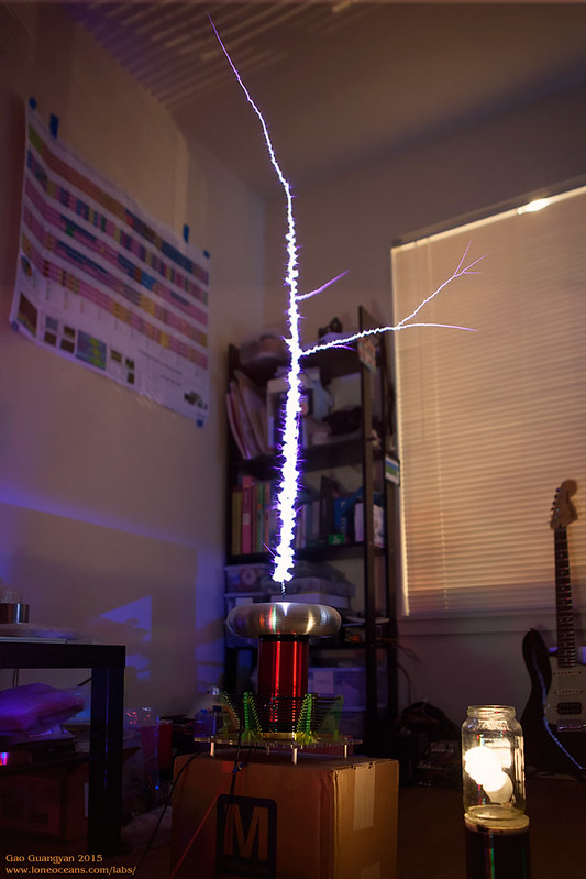
It seems to work! The current was still kept just around
150A+, but the pulse width increased to 15ms. This led to significantly
straighter and hotter sparks, though with not much improvement in spark
length. Increasing the pulse further made the sparks much fatter but no
increase in spark length. It seems like generating 5 feet of spark would
require 200A+, which should be capable with my current bridge. Time to
begin with the next experiment with a large toroid and a system with
higher coupling! Spark length is just about 4 feet, which is still
unfortunately nowhere near the 60" required to break 10x secondary
length!
This calls for more work...
02 Jun 2015
Experiment 2 - "FAT TOROID"
The new secondary coil design was doing quite well, but
still not performing as well as I wanted. Based on my measurements, I
went back to the drawing table, sat down and crunched some numbers. It
seems that one of the main limiting problems
of my current setup was due to spark de-tuning and insufficient coupling,
causing a poor impedance match between the inverter and the spark load. So a
new primary coil and toroid was constructed. After initial phase lead
tuning at around 408kHz, I started testing the new setup.
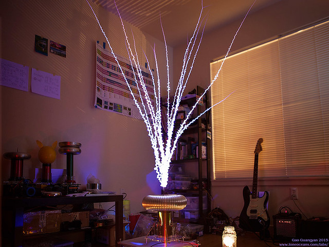
Initial results were very promising! For the first test
for the new fat toroid system, the pulse was set to be 20ms long going
up to around 250 - 260V, with a measured peak current around 125A. Even
so, it was easily producing just over 4 feet, maybe 4.5' of spark. Buck
switch frequency was around 9.6kHz up to 26kHz. The primary coil was
tapped around turn 10.2, upper pole operation from about 413kHz to
386kHz and a pulse energy of around 162J (330V to 276.3V). Shorting the
pulse to 15ms produced roughly the same results but with less overall
bang energy.
During this test I also encountered several instances
where the buck did not regulate well, possibly caused by noise (and also
because the resonator was now placed directly above the electronics),
causing the desat detector to kick in more often that I would like. In
addition, due to the higher impedance setup, startup was sometimes not
too reliable at low bus voltages. The buck circuit will need to be
re-worked for the next coil :-). (read below - has been fixed)
There is still headroom for more bus voltage, so the
plan for the next test of Fat Toroid will be to charge up the bus capacitor to 400V
(right on the limit) with a ramp reaching 325Vpk, which should give
around 272J per pulse, and a max current should be around 160A.
Hopefully this will allow for even better spark growth.
15 Jun 2015
After the promising results with the new FAT TOROID
geometry, I tidied up all the wiring and did some tweaks. Previously my
buck converter was glitching sometimes resulting in some unusual
behavior, and I eventually found that the problem was due to me
overlooking the input ratings of a comparator. I fixed this problem and
adjusted the buck feedback for higher switching frequency hoping to get
a smoother ramp.
This finally paid off, and I'm proud to say that QCW 1.5
is now performing about as well as I can hope for with the exact
impedance match I was looking for, delivering 150A at its peak ramp of
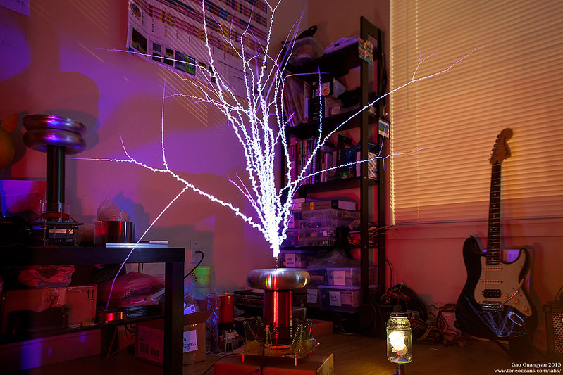
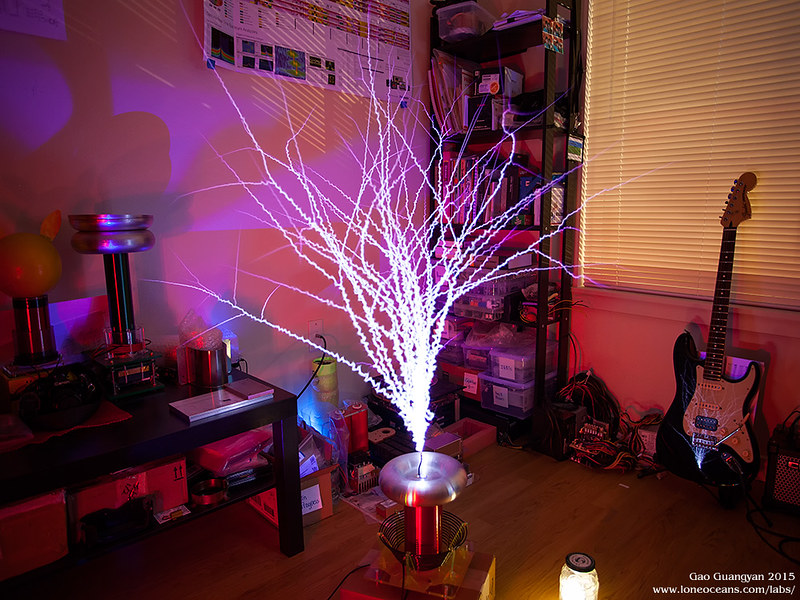
just over 300V. Spark length is now just over 70", and I have exceeded
my project goals more than I could have hoped for with an almost 13:1
spark to secondary length ratio!
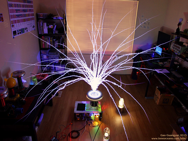
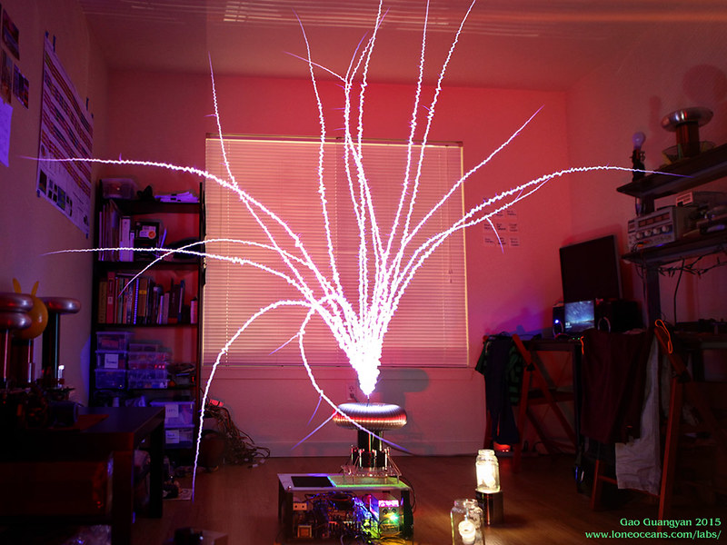
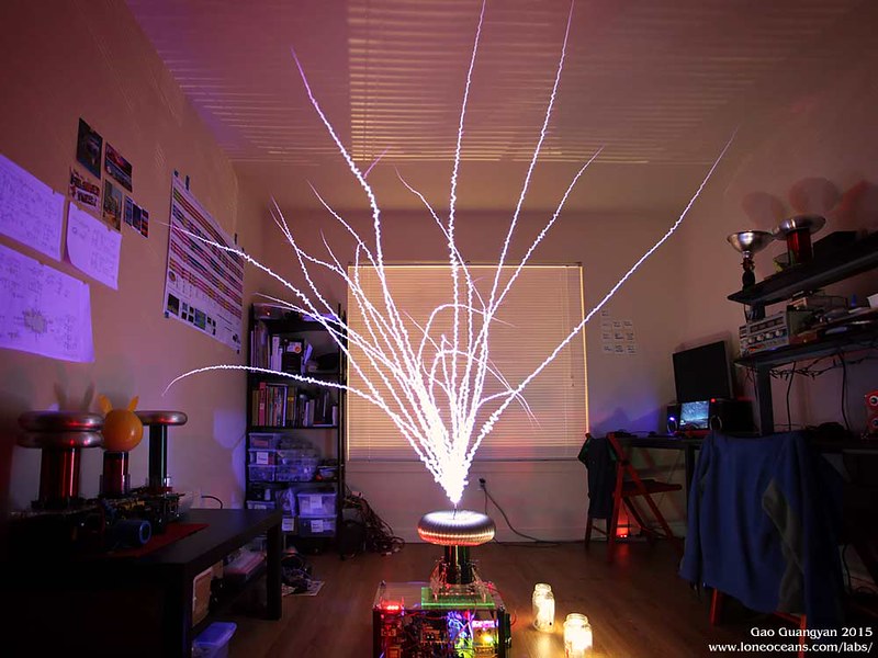
Running parameters are as follows: The bus cap is charged to about 385V with a
ramp up to just about 300V (from ~75V). Peak current hovers between 145
to 160A, with an operating frequency starting at 413kHz dropping to
about 377kHz with a ~70 inch long spark.

The new buck switch frequency is around
16.5kHz up to 31.85kHz (really depends on operation though). Pulse duration around 22ms with a rising ramp
around 16-17ms. Each pulse consumes about 275J. The primary current
waveform is most interesting. There are still some further tweaks I will
be making soon, including lowering the initial ramp.
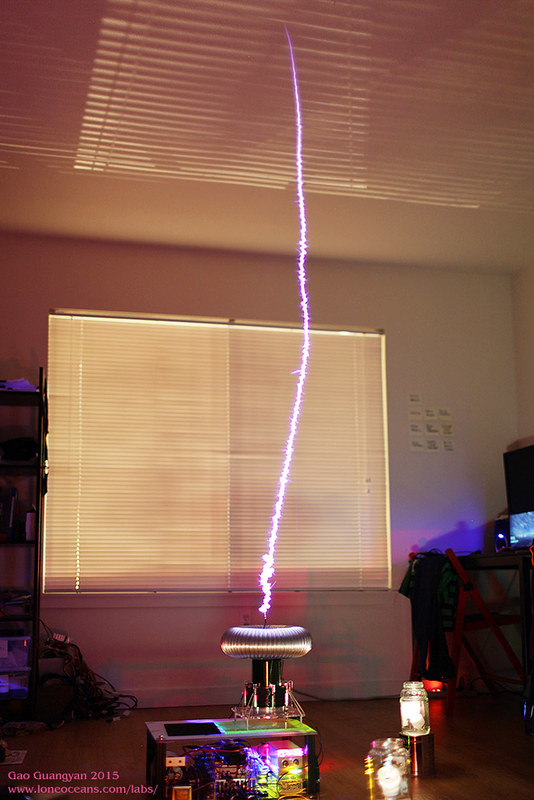
Right now the coil is running fairly reliably with
excellent performance :). Above is a lucky single shot capturing a very
beautiful straight spark. I'm sure I can tweak the ramp parameters just
a few more inches of spark length output, but at this point I'm probably
limited by my bus cap which is running out of capacity, so I think just
about 6 feet is the limit at ~160Apk with this setup.
At this point I think I can call QCW 1.5
complete!
Thanks for following this page and be sure to check back
for the next project. It's probably going to be a QCW 2.0 :-).
Credits
I would like to thank the following people, for this
project would not have even started without their inspiration and help.
- Steve Ward for his advice on my QCW design (and for
coming up with the first QCW DRSSTC)
- Udo for his advice and in helping in calculations
for impedance matching and suggestions
- Most of the photos here hosted on Flickr to help
save on my limited bandwidth
- And everyone else who has helped me in one way or another.
See my original QCW 1.0
page for the original build.
As usual, more to come soon!
Back to main page
(c) Gao Guangyan 2026
Contact: loneoceans [at] gmail [dot] com |

