loneoceans labs | 80mm Full Bridge + V1.1 (temporary placeholder page)

The 80mm Full Bridge + is a fully integrated, compact full-bridge system for DRSSTCs and other inverters for Power Electronics projects
The 80mm Full Bridge+ is a compact, full featured, yet simple to use general-purpose H-Bridge platform. It is fantastic for simple, small DRSSTCs and SSTCs. This board has been also used to over 3kW continuous operation with a fan for cooling.
It was designed for use in all kinds of power inverters, though originally created for use in my Solid State Tesla Coil projects. The idea was to be able to quickly pick up a general purpose H-Bridge, pair it with a suitable driver, and have a Tesla Coil ready to go! The Full Bridge Plus can be used in SSTCs, DRSSTCs, high frequency transformer drivers, and so on. The original 80mm Full Bridge board (non-plus) was conceived to be a general purpose H-Bridge which would work well for small / medium Solid State Tesla Coils, and consisted only of the bridge section. This Plus version is an improvement over the original design. It adds on-board bus capacitors, as well as a bridge rectifier, fuse, current-sense transformers and a bus-bypass capacitor. This result is a truly all-in-one system - just grab a coil driver and you're almost done building your coil!
The system also features off-the-shelf Gate Drive Transformers* - no need to worry about winding your own, and is designed to work with four TO-247 of your favourite transistors. For optimal thermal performance, all transistors and the bridge rectifier are designed to be mounted with individual and commonly available 28mm square heat-sinks. A common 80mm computer fan provides cooling.
The result is a completely integrated design which works together with an
external MMC and driver to form a complete (DR)SSTC. The FullBridge+ works great
with the Universal Driver V2.7.
* Your coil system needs to work within the requirements of the GDTs used (i.e.
the V-us, make sure it doesn't saturate). Otherwise, you will have to use your
own external GDTs.
![]() The
80mm FullBridge + system including design, schematics, layout and design are available
on this page
under the Creative
Commons License.
The
80mm FullBridge + system including design, schematics, layout and design are available
on this page
under the Creative
Commons License.
80mm Full Bridge + V1.1 has the following features
Version 1.1 - Aug 2018 - Adjusted screw terminals positions for better
fit (v1.0 had very slight interference with bridge rectifier, just need to cut
the screw terminal legs after soldering) - This is the most updated version.
Version 1.0 - Sept 2017 First run of PCBs
These boards are currently being offered as a bare PCB shown as such:

This board was designed as a personal project and may not work with your set-up. Please note this board was designed solely as a personal hobby board for myself, and potentially interfaces with deadly mains / line voltages! I make no claims that the board satisfies any UL, CE or any electrical standards. You will bear all responsibility for using this board correctly and safely in your project with good engineering practices and safety as its utmost priority.
Shipping is from the USA to anywhere around the world (not included but usually relatively cheap) starting at $4.50 for regular mail, $9 for USPS Priority Flat Rate and starting at ~$15+ for international orders (subject to change based on mail rates). All prices are in USD.
Contact loneoceans [at] g mail [dot] com for enquiries.
Schematic

Schematic for the 80mm FullBridge+ is above for reference. Note that the TVS diodes (labeled T1 to T4) are bi-directional transient voltage suppressors and have their schematic symbol incorrectly drawn above.

Layout for the 80mm FullBridge + is above for reference.
Component List
These are the recommended components required for using with them 80mm FullBridge+. Components are available on Digikey or Mouser or your favourite electronics supplier. Feel free to substitute them with similarly-rated components to suit your needs, or if some parts are backordered.
Main Board Components
- Q1, Q2, Q3, Q4 - Your favourite TO-247 IGBTs or MOSFETs x 4
Recommended options include FGA60N65SMD, FGH60N60SMD, IRGP50B60D1,
IRFP460
- GDT1, GDT2 - GT04-111-063-B or P0584NL x 2
- B1 - GBPC-W Bridge Rectifier 600V 35A - GBPC3506W-G - 1
- C1, C2 - Decoupling PP Capacitor - 560V 2.2uF 32x13mm 27.5mmLS R46KR422000M2M
x 2
- C3, C4 - Bus Capacitor - 400V 820uF 35mm dia. 10mm LS ESMR401VSN821MA45S
x 2
- C5 - Bypass PP Film Cap, 18 x 9mm x 15mmLS, 600VAC 68nF - B32642B0683J x 1
(This capacitor acts as a bypass capacitor to protect the primary
coil against primary strikes by creating a low-
impedance path for the arc to go to ground) - not required
for non-Tesla Coil uses.
- F1, Fuseholder - Schurter 0031.8211 x 1
and 20x5mm fuse - 15A time lag ceramic (0215015.MXP) or glass
(0218015.MXP)
- R1, R2, R3, R4 - Gate Resistors - 1206 package, 5 to 20 ohms depending on your
design x 4
- R5 - 10kR 6.5W MMC Discharge Resistor - CW00510K00JE73 x 1
(This resistor discharges the MMC through the primary coil
between pulses. It helps in the initial start-up of
the bridge when driven with a UD2.7C. Not required for
non-SSTC designs).
- R6 - 100kR 1W Bleeder Resistor - ASRM1JA100K x 1
- D1, D2, D3, D4 - Schottky Diode DO214AC/SMA - SS14-E3/5AT x 4
(Allows IGBT turn-off to be faster than IGBT turn-on, due to
long current tail of IGBTs. This prevents shoot-through
conditions. Could be omitted when used with some
MOSFETs, or replaced with Diode+Series resistor).
- T1, T2, T3, T4 - TVS Diode DO214AC / SMA 26V Bidirectional - SMAJ26CA x 4
- X1, X2, X3, X4 - 5mm Pitch 2 Position Terminal - Wurth 691102710002 x 4
- X5 - 5mm Pitch 3 Position Terminal - Wurth 691101710003 x 1
- CT1, CT2 - Triad Magnetics Current Transformers - CST206-1A/2A/3A for
1:100/200/300 x 2
(For easy connection with UD2.7C Driver)
Other Components
- Spade Terminals to bus and outputs (optional) - 0.250"
Faston Tab 63839-1 x 4 (and connector 640905-2)
- 80mm computer fan of your choice - for example, pick a 24VDC fan for use with UD2.7 driver,
with a 24VDC power supply
- Stand-offs of your choice, nylon recommended, 1", mounting holes are big
enough for 6-32 or 8-32 threaded
stand-offs
- Thermal paste for heatsink to TO247 transistors
- Various mounting screws of your choice and and recommended nylon
washers (pick suitable size for your needs)
- Additional stand-offs for mounting assembled system (up to 8 threaded
stand-offs, recommended 8-32 thread)
Recommended Heatsinks to use
The most versatile ones are the 28 x
28 x 20mm heatsinks available very cheaply on Ebay. You can also use one
of these 28mm heatsinks for the bridge-rectifier. Another good option are
37x37x24mm heatsinks.
- 28 x 28 x 20mm heatsinks on
eBay (x4 for each TO247 Transistor)
- 37 x 37 x 24mm heatsinks on
eBay (x1 for the bridge rectifier)
The photo on the left shows the common 28x28x20mm heatsinks. These can be used for the IGBTs/FETs as well as the bridge rectifier. You will need to drill and tap holes yourself, typically for a M3 screw. Alternatively you can also purchase ~34x34mm heatsinks for the bridge rectifier, available also on Ebay or Aliexpress. These come with a threaded hole already.
Notice that the 80mm FullBridge + system uses individual electrically isolated heatsinks for the main power transistors. This ensures optimal thermals with no need for sil-pads such as when used in a common-heatsink design. The board features mounting holes for stand-offs to mount a common 80mm fan to blow directly on the heatsinks ensuring excellent thermal performance!
Gate Drive Transformer and Resistors
Choosing the Gate Resistor for the transistors depends greatly on your system design including choice of transistor, gate drive voltage, frequency, and so on. When using FGH60N60SMD IGBTs, typically a 15 ohm resistor is a good choice for 24V gate drive, or 10 ohms for 12V gate drive, in ~300kHz DRSSTC operation.
Note that the Gate Drive Transformers used in this design will work for ~200kHz or higher operation. However when driving coils of lower frequency, you will have to wind your own Gate Drive Transformer. Ensure that the Volts-uSec of the transformer is not exceeded. If a frequency too low is used, you will run the risk of saturating your GDT leading to IGBT failure. Please refer to the datasheets here or here for more details. As an example with the GT04-111-063-B, this has a ET product of 63Vus. The ET can be calculated as:
ET (Vus) = V_gateDrive * DutyCycle / Freq(MHz)
As a result, using this transformer with a 24V gate drive, 63Vus = 24V * 0.5 / Freq, Freq = 190.5kHz is the minimum frequency before transformer saturation.
Assembly of the 80mm FullBridge +
Assembly of the bridge is straightforward and easy. It is recommended that the TO-247 transistors be mounted with heat-sinks screwed in place, before soldering down.

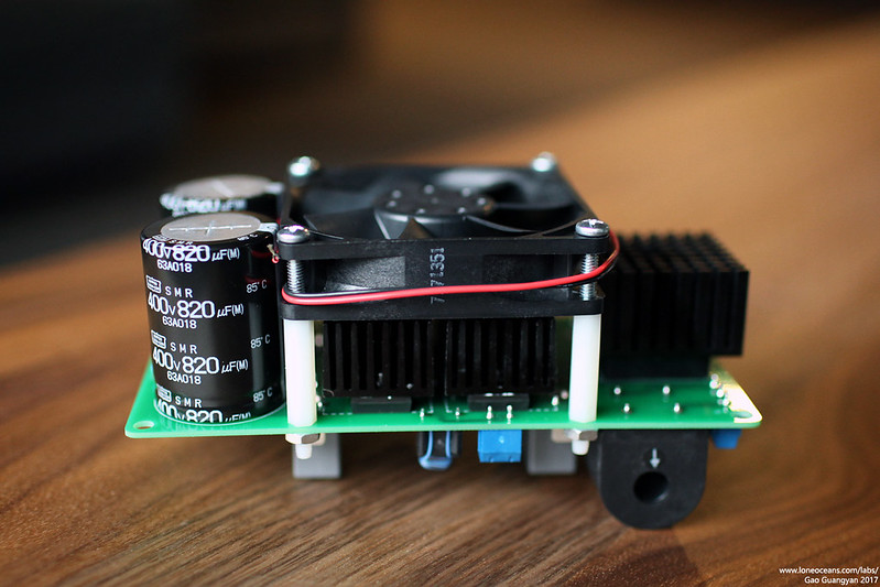
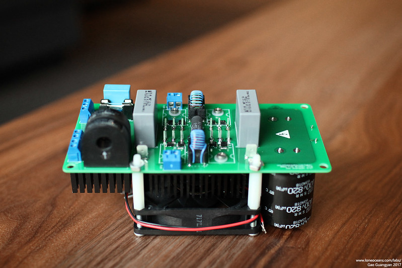
Above shows an example of the completed Full Bridge Plus. Note the four 28x28x20mm heatsinks on the TO-247 transistors. I also used a 37x37x24mm heatsink for the bridge rectifier. A 24VDC fan is mounted for cooling of both the transistors and the heatsink. If you use the same design, you can use a 1-1/8" 6-32 or 8-32 nylon standoffs.

It is not necessary to cut off the leads of the TO-247s since this arrangement allows easy probing of the gate drive signals etc. For mounting of the PCB, you can use roughly 2" or ~50mm standoffs on the 4 corners. Note that if you do that, be sure to cut a hole below the fan to allow air flow.
Design & History
The 80mm Fullbridge + is an upgraded version of the original 80mm FullBridge which was designed specifically to be a compact full bridge.

Above shows the original 80mm FullBridge design with integrated heatsinks, and shows its size compared to a UD2.7C DRSSTC Driver. The FullBridge+ adds on to this by adding an on-board high power rectifier, bus capacitors, a fuse, bypass capacitors and connectors for an even more integrated design.
===
For more enquires, please contact me at loneoceans [at] gmail [dot] com.
Back to loneoceans labs. (Updated May 2024)