|
Mini 40mm Tesla
Coil
Index
|
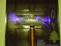 This project was
inspired by all the other tesla coils out there. Since it is
my first attempt at building a tesla coil, my aims are
to produce a small, relatively good-looking,
working spark-gap tesla coil, more to learn about building
tesla coils, and to gain invaluable experience. This project was
inspired by all the other tesla coils out there. Since it is
my first attempt at building a tesla coil, my aims are
to produce a small, relatively good-looking,
working spark-gap tesla coil, more to learn about building
tesla coils, and to gain invaluable experience.
This page will index my
construction efforts as I update it continually during the
course of my tesla coil construction. It will be updated
frequently, with the most recent ones at the bottom.
Current Status: Under
Construction.. Completed! on 20th November 2003
Now under testing and tuning...
Project status halted since 2004 till further notice (28 July 2004)
Coil currently being improved. (9th August 2004) |
|
 Acknowledgements Acknowledgements
The tesla coil is
complete! I would like to thank the following people, for this
coil would not have been completed without them.
- The great people at
the 4hv forums and the-geek-group forums for giving me great
advice and suggestions
- My dad and my mum who sponsored most part of the funding for
the building of this coil and for finding parts and components
together with me, and for spending time and resources, and for
tolerating the noisy coil while in operation.
- All the great tesla coils on the internet which gave me
valuable advice and construction details
- And everyone else who has helped me in one way or another. |
15 Oct 2003 (Wednesday)
|
 I
have recently acquired a Neon Sign Transformer for my power
supply. It's the unit on the left. I passed by a Neon Sign
shop and asked for a used/old/spoilt transformer. Luckily,
they had some extras. After much persuasion, they gave me a
supposedly spoilt unit. I
have recently acquired a Neon Sign Transformer for my power
supply. It's the unit on the left. I passed by a Neon Sign
shop and asked for a used/old/spoilt transformer. Luckily,
they had some extras. After much persuasion, they gave me a
supposedly spoilt unit.
It is a F.A.R.T. brand
transformer. (stands for Fabbrica Apparecchiature
Radioelettriche Treviso I think.. this is living proof that a
brand this name can sell so well. It is the best selling neon
sign transformer in the UK by the way.
www.fart.it). It's a 15kV
30mA unit, and weighs around 7+kg. The whole thing is potted
in a resin block and comes with a zinc mounting plate. This
design eliminates rusting and is a very sturdy transformer.
Anyway, I went home and
tested it. Apparently, only one secondary winding had shorted
but the other half was in working condition. This makes it put
out approximately 7.5kV 30mA. Just what I was looking for, for
my small coil. 15kV would be a bit on the high side. Although
this makes it not a very powerful unit (especially since half
of it is junk and taking up extra space), it is still
relatively small and delivers 225Watts with this
configuration. I hope to get around 1 foot arcs from this
system. However, I did not receive any High Voltage cable, so
I guess I'll have to go find some... I'd probably be using
this unit for my coil, unless I find another one in better
condition.
To test if it was
working, I hooked up the mains and powered it on with half of
the high voltage windings. Btttztztzzttzz! It works! At least
I know that this thing can output the 7.5kV at 30mA I need.

Here is the picture of
the arc. 30mA is quite high (quite enough to kill!) resulting
in a HOT fiery arc. I will make a large Jacob's ladder too to
celebrate this find! At least I got this transformer Free.
Tomorrow, I plan to buy materials for my
toroidal top load... I have acquired a large roll of aluminum
tape for $15. I would be constructing the top load and
hopefully the spark gap (set at 8kV) tomorrow. |
18 Oct 2003 (Saturday)
|
Progress has been slow
due to the un-availability of parts... until now. I have
finally got most parts more construction can start. I've
decided on a double toroid design, one large diameter one
resting on a small diameter toriod, for better E-field
shaping.
Toroid


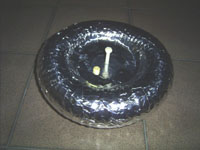
PVC Corrugated Drain Pipe : Larger toroid taped up....
: Complete small toroid with nylon screw.
The small toroid took
around 2hrs to make. The small one is approximately 23 x
5.5cm. (23cm being the total diameter and 5.5cm being the pipe
diameter). A commercially spun toroid would cost well over
$100 new. Building this cost less than $20 and is extremely
simple to make.
 Constructing the toroid..
The first thing I did
was to cut the centre disk out of some surplus plastic I had
lying around. It's about a 12cm dia disk. After cutting with
my saw, I drilled holes around the perimeter of the disk at
roughly 1 inch intervals. These holes will hold the wire used
to tie the PVC pipe to the disk. After coating the disk with
aluminum tape (plumbers tape), I tied the pipe to the disk.
The pipe I used is a 2" Flexible PVC drain pipe.
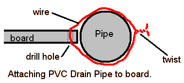
I just bent the twisted
wire into the grooves of the corrugated PVC pipe. The pipe
will automatically fit around the disk :). It's not that easy
as it looks... Following that I taped the whole pipe up
with masking tape, to provide a smoother finish, and finally,
the aluminum tape. Basically.. it's done! I bought some nylon
screws to attach it to the secondary coil. The larger coil is
still needs to be wrapped with aluminum tape. Over here,
flexible corrugated PVC pipe and aluminum tape don't come
cheap. I thank my parents for supporting me financially :).
That's it for today. I'll continue the other toroid tomorrow.
It's a nice smooth
toroid after smoothening it with the back of a spoon. |
19 October 2003 (Sunday)
|
I completed the toroids
today and fixed the spark-gap together. The spark-gap is not
fully completed as I still need the fans and attach them to
the gap to quench the sparks. More than 4 hours of work today.
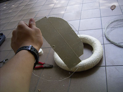
Here is the 2mm acrylic disk to be fitted in the middle of the larger
toroid, which has been taped up with masking tape to smoothen
out the ridges. The disk is approximately 21cm in diameter.
The toroid is about 32cm in diameter, and is made from the
same material as my smaller toroid (2" corrugated PVC drain
pipe). Here, the acrylic is being taped up with aluminum tape
using the same method as my smaller toroid.
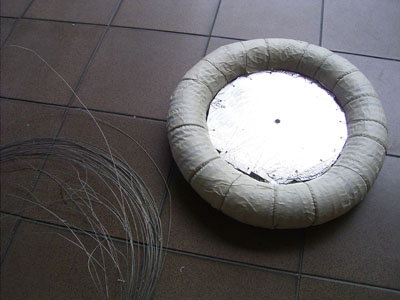
Looking good.. disk has been attached with
wire to the torus.
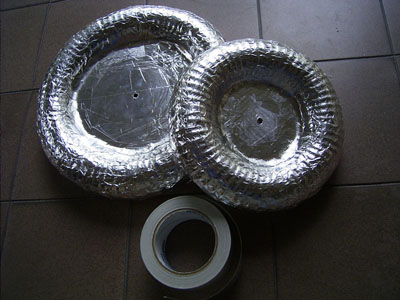 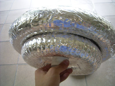
Both toroids completed! Everything is
screwed together to a PVC end cap with a nylon screw. Both
toroids took a total of 4 hours to construct. Sure beats
spending a few hundred bucks.. :) There's nothing much to do
after the examinations anyway. The PVC end cap is to
facilitate easy attachment to the secondary coil. Not bad for
my first attempt at toroid making..
Later in the afternoon,
I got more materials and built the spark gap. It's a basic
sucker-gap design, using two copper pipes as the main spark
gap all housed in a plastic box with two fans to quench
the arcs. I realised that those white plastic chopping boards
would be much more ideal than acrylic. It costs two times
cheaper for the same size (if not bigger) and is a whole lot
easier to saw. I only have a lousy hand saw.. a Jig-saw would
save lots of time... Here's my design.
 It's
really very simple. The plastic box houses the two copper
pipes, electrically connected internally to the threaded rods
holding it to the box. The two square holes on the side of the
box are made to accommodate standard computer 80mm fans. It's
really very simple. The plastic box houses the two copper
pipes, electrically connected internally to the threaded rods
holding it to the box. The two square holes on the side of the
box are made to accommodate standard computer 80mm fans.
I have a 4Amp power
supply for the fans so it shouldn't be a problem even for high
powered fans. At the low power my tesla coil will be running
at, it shouldn't get too hot at all.
It's looks easy to
build, but it's not without proper cutting equipment :(. The
whole gap took around 2 hours to make, except for some places
which need to be covered up and another fan. The air must be
forced only in between the spark gaps due to the limited
amount of air flow I can get with the fans.
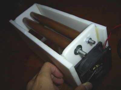
Here's the uncompleted spark gaps made out
of chopping board plastic, 22mm copper pipe, threaded rods,
contact cement and hot glue. The copper pipes are 22mm, 200mm
long each, and the whole cap is 10cm wide. Looking good too
:).
Looks like today has
been a rather successful day. I can't do much during the
weekdays due to school, so I'll have to cram more stuff during
the week ends. I am now left with the filter network,
capacitor bank, secondary coil, primary coil / supports...
lots more work to do. I am thinking of fitting all components
inside a nice box.. |
21 Oct 2003 (Tuesday)
| Not much done today. I made
a simple poor-man's rig and after drying my 40mm PVC coil
form, I varnished it with polyurethane. The set up is
basically a wooden rod through the PVC, stuck with duct tape,
and tied in between 2 chairs.
 The
handle is a piece of thick wire and a short copper pipe. The
handle is a piece of thick wire and a short copper pipe.
This allows me to wind the PVC as I
apply the varnish. It's not as easy as it looks. Anyway, I
kept rotating the pipe for about an hour with a fan blowing to
allow it to set before I let it dry for the night. It's
tiring..
Although it's not smooth, I'm going to
fine-sand the uneven parts down before I can wind my secondary
coil!
|
24 Oct 2003 (Friday)
| I completed the Primary
coil today. I have acquired a
Black & Decker 400W jigsaw. It really saves a lot of time.
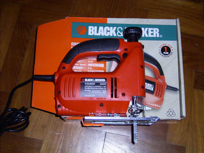
No more messing around will puny hand saws, this is THE
machine! :)
The base is made of a
230x230x6mm clear acrylic surplus piece I had lying around. I
made 4 supports, each with 9 spaces for the primary windings
and 1 extra should a strike rail be needed to install. The
stands are made out of 12mm thick white plastic chopping board
material. (It's cheap and easy to get from the mart) and are
attached to the base with contact cement and hot glue. The
coil is made out of 3mm thick flexible copper tubing.
Everything was cut and drilled by hand, and even with the help
of the jigsaw, it still took around 2 hours to plan, cut and
fix the mistakes. Here are some specifications:
Primary Coil Inner
Diameter (from the copper tubing): 10cm
Primary Coil Outer Diameter (from the copper tubing): 24cm
Height at outermost turn of coil: 4.5cm
Height at innermost turn of coil: 1.5cm
Copper tubing conductor diameter: 3mm
Inter-turn spacing of copper tubing: 6mm
Total number of turns: 8.5 turns
Geometry of Primary coil: Inverse conical with a 15 degree
slope.
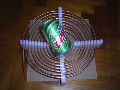
So here it is with a can
for comparison. The back protective layer of the acrylic
hasn't been peeled off yet, which is why it looks brown. I
have attached a 40mm PVC end cap with a nylon screw to the
centre of the coil to allow easier connection of the secondary
coil to the primary coil. Not too bad for a beginner.. |
7th Nov 2003 (Friday)
|
Again, due to lack of
parts, I was unable to continue. Yesterday, my dad helped me
purchase 30 capacitors, High-Voltage rated resistors and 0.2mm
enameled copper wire. I purchased acrylic and thick wires
today, so work can finally begin again.
Today, I completed the
primary capacitor bank using a MMC (multi mini capacitor)
setup. The capacitor is a critical element in the tesla coil.
Critical because it is really punished by the oscillations of
the Tesla tank circuit. The tank current can easily reach a
value of several hundred amperes. The RF (radio frequency)
produces intense stress on the dielectric of the cap.
Professional pulse discharge caps with the values needed for
Tesla coil circuits usually cost between $300 and $1000
(depending on the capacitance and voltage value). So most
coilers try make their own. One of the best approaches is to
connect many small pulse caps in series/parallel and build a
MMC. This seems to be the ultimate solution as a 20nF unit
rated for 10kV in tesla coil use cost below $50 when build
this way - and this is a perfect cap build by professionals
(at least its components), which is why I chose to make a MMC.
According to The Geek
Group's capacitor design chart, the resonant cap for a 7.5kV
30mA transformer at 50hz is 0.0127uF. However, a LTR (Larger
Than Resonant) Cap of a desired value of 0.0191uF(19.1nF) is
recommended - LTR caps reduce the chance of over-volting the
capacitor and transformer, as well as increasing the bang size
and power throughput. In other words, thicker, longer sparks
with less chance of damaging components.
After searching, I
located some nice 1.5kV 0.047uF Film-Foil Polypropylene Axial
Capacitors. They have a very low loss dielectric suitable of
continuous use at high AC voltages and will withstand fast
rise time pulses, as well as having excellent high frequency
performance, exactly what is needed for a Tesla Coil Cap.
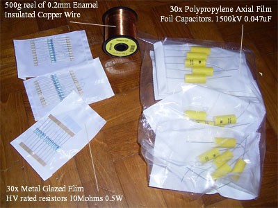
After calculating, I
acquired the above components. The 10 Mega Ohm Metal glazed
High Voltage resistors are wired to each capacitor to drain
off the charge after use to prevent shocks, as well as to
regulated the voltages.
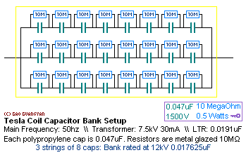
Here's how I wired up
the capacitors. The MMC consists of 24 Capacitors, 3 strings
of 8. The final value of the whole cap bank is rated at 12kV
at 0.017625uF (17.6nF), close to the LTR value of
0.0191uF.

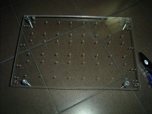
Everything is drawn out nicely on the acrylic
sheets.. and they are drilled and cut all by hand.

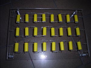
The capacitors are slotted in... and their ends
are wired up in series.

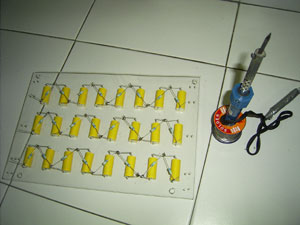
Than the resistors go in.. and they are
soldered up together.
 The completed capacitor bank!

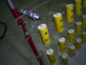
Details of the competed bank.
The bank was mounted on
a 6mm clear acrylic sheet with a 5mm backing. I have to fix
the termination connections at the end of each capacitor
string. My current 40W soldering iron just can't heat the
large copper cable hot enough for the solder to stick.
The completed bank is
visually appealing :-) and took around 3-4 hours to construct.
It cost less than $40 to build - much cheaper than a few
hundred dollar pulse capacitor... |
9th Nov 2003 (Sunday)
| I completed winding the
secondary coil today. My coil form
is a 40mm diameter white PVC pipe. It has been dried and
sealed with polyurethane varnish before winding. I have
decided on a 1:6 winding ratio to add more turns in the
secondary, and to allow use of slightly thicker wire (thin
wire breaks too easily). I used 0.2mm wire (about AWG32?) and
wound about 24cm (actually 23.6cm). With 95% fill, I get about
1100+ turns. The whole coil was wound by hand and took around
1 hour plus.
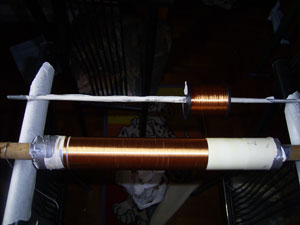
Above is the poor-man's
winding setup.. I threaded a wooden dowel though the PVC form
with cardboard end supports and the whole thing was kept in
place with duct tape. It was then tied to a chair with wire,
and was allowed to turn freely. (Okay, not so freely... ) The
0.5kg (about 1600m of wire) reel was supported by a surplus
metal rod and could spin freely too. I taped the ends of the
wire with duct tape.. not that nice but at least it works and
sticks well. I'll just varnish over everything in the end...
Winding was tiring especially for the fingers but it was all
over in about an hour.
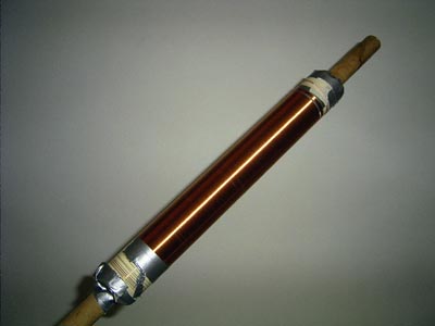
My first complete coil!
It shines like a copper tube! As you can see, I've left quite
a bit of extra wire at the ends. As I write this, the coil has
been fully coated with polyurethane and is drying. I plan to
put 4 to 5 thick coats, with fine sanding in between each
coats to remove irregularities and give the coil a smoother
finish. |
10th Nov 2003 (Monday)
|
 I
have completed coating 4 thick coats of polyurethane varnish
for protection. Due to my lousy coil setup, thick bristled
brushes and lack of skill, the varnish did not apply smoothly,
and there were lots of irregularities (high areas) which
provided a lumpy feeling. I wet sanded before the 3rd and 4th
coats. However, the secondary finish was not what I hoped for,
clear and smooth, but had a sort of 'rusty gold look..'
However, it still provided thick insulation which was what it
was meant for. I
have completed coating 4 thick coats of polyurethane varnish
for protection. Due to my lousy coil setup, thick bristled
brushes and lack of skill, the varnish did not apply smoothly,
and there were lots of irregularities (high areas) which
provided a lumpy feeling. I wet sanded before the 3rd and 4th
coats. However, the secondary finish was not what I hoped for,
clear and smooth, but had a sort of 'rusty gold look..'
However, it still provided thick insulation which was what it
was meant for.
On the left you can see
a mock setup. Nothing is connected yet, it's just stacked up
together. You can see the 15 degree inverse conical primary,
the secondary coil and the double toroid configuration. The
coil is meant to be pushed fully in the end caps for a quick
and easy attachment. Now it somewhat balancing...
The toroid is clearly
not so smooth.. I have tried smoothening it out but it's not
working very much. I shall see how it works out first. |
13th Nov 2003 (Thursday)
|
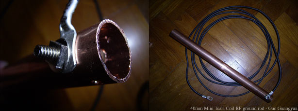
I made the RF ground rod
today. It's a 22mm x 1' long copper tube. The wire is 3m, 6mm2
7 wire stranded PVC insulated wire and is connected to the
copper tube with aluminum wire lugs with a stainless steel
screw and nut.
I have also made a
safety spark gap consisting on threaded rods, nuts, hex end
caps and a plastic container.

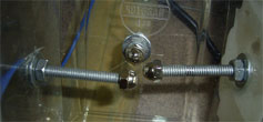
It's a simple but
effective design, and can be easily and accurately tuned.
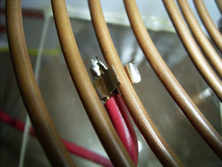
This is the primary tap made out of a fuse
holder. There's quite a lot of surface contact, and is very
easy to tap.
Almost everything is
done and all I am left with is the tuning and connections! I
can't wait to fire it up!
|
20th Nov 2003 (Thursday)
|

This is my more-or-less
finalized design. Above is the schematic of my coil.
-
Mains is 240VAC
50hz with a 13 Ampere circuit breaker - More than enough
power!
-
I am using a 3 Amp rated EMI filter for
240VAC. Again good enough.
-
The variable autotransformer (variac) is
a 500VA model. I mostly use it to tune my spark gaps.
Apparently, the variac seems to be restricting current flow
and my coil performs better without the variac.
-
I got my Neon Sign Transformer free from
a neon shop because it was 'spoilt'. It's a 15kV 30mA unit
and half of the windings got shorted out, so I am using half
of it, 7.5kV 30mA and the other end is sealed up.
-
(s.g.) is the Safety Gap to protect my
capacitors and the neon sign transformer.
-
L1 and L2 are chokes, basically insulated
wire (same wire as my secondary coil 0.2mm) wound 1 layer on
a pen tube. This prevents the high frequency AC from
traveling back to my transformer. However, I have been
informed that it is not needed and the coil will work
perfectly well without it, so I left it out.
-
(m.g.) is the Main spark Gap made out of
two long copper pipes which can be accurately tuned.
-
C1 is my main MMC design capacitor bank
rated at 12kV 0.017625uF (17.625nF).
-
(p.c.) is my Primary Coil with 8+
tappable turns. I used a small diameter fuse holder as an
adjustable tuner.
-
s.c. is the secondary coil.
-
The toroid is a double toroid design for
more capacitance and to improve electrostatic field shaping.
construction was
completed this afternoon...
*** First
Light! ***
I completed all the
connections and fixed everything up in the backyard.
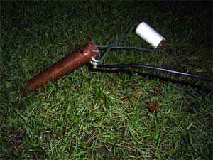
The 1 foot long RF copper ground
rod is hammered into the soil.. connected to the coil with a
3metre long 6mm2 cord.
Arcs Pictures
(first few lights. Click to enlarge photos)
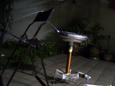
This is really the FIRST light, without any
tuning. It maxed out 5cm arcs.. not very good.. but it
works... (click to enlarge)
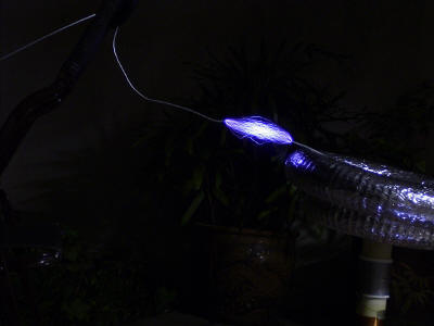
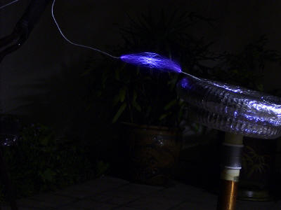
After tuning..: 10cm and 15 cm arcs. This is
after tapping the secondary at turn 6. At first light, it was
as turn 8. Spark length, brightness and noise improved a lot.
This coil can make small fluorescent bulbs light up dimly
nearby. However, I am still not satisfied. There is NO
breakout from the toroid, and with a breakout point, thin,
purple, corona like discharges can be seen. The arcs are
really thin, and I believe my spark gap is set too small.
However, It was time to pack up. I'll do more work soon! I aim
at least 40-50cm arcs! My coil is surprisingly quite
quiet.. I think it's my spark gap. I have fans at my spark
gap, but they have mysteriously stopped working. Now I am
running the gap without the fans for quenching for now..
(click to enlarge)
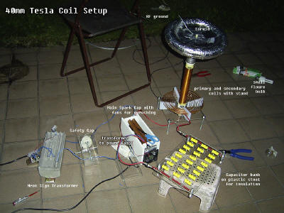
Here's the setup. Await
better news for the next firing! (Click to enlarge)
Today's maximum arc length from breakout
point to RF ground : 17cm |
22th Nov 2003 (Saturday)
|
It's SECOND LIGHT today!
Thanks to the people at
www.4hv.org (4hv forums) and
www.thegeekgroup.org
(geekgroup forums) for helping me debug and give suggestions
to improve performance of my tesla coil.
*click on pictures to
enlarge. Due to long exposures, there is significant 'noise'
in the photos.
 Everything
is set up and ready for the second run! Everything
is set up and ready for the second run!
Here are some changes I
made:
1. Nice High Voltage
warning sign made
2. I widened the spark gap
3. Coil is now tapped at 5.75 turn at the primary coil
4. Sparkgap is still running without the fan.
So far, the sparkgap and
safety gap is holding up fine.
One design flaw I have
is that the secondary height cannot be adjusted to fix
coupling. Also, I did not make a portable cabinet with wheels
to move it around.. However, it is quite well mounted. I am
pleased with the toroids. Using only one toroid instead of two
led to small arcs.
If I could make changes,
I would try to fix:
1. The power supply. I
believe 7.5kV at 60mA would produce much thicker arcs. My
current arcs are very thin and fine
2. Portability. I have to lug everything around, wires and all
everything I want to fire it up. Packing it is also
troublesome
Now, the sparks.
Everything is the same as run 1 except for the increase space
at the sparkgap and the primary is tapped at turn 5.75 instead
of 6.5 / 6 of the previous run. Second light.
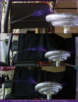
Click to view in full! There is finally
breakout from the toroid! (none on run 1). Arcs are still
wimpy and thin, but they are significantly longer. The coil
runs louder and fiercer too.
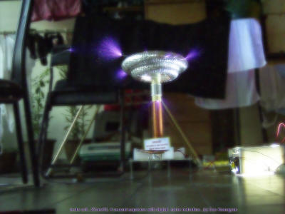
This is a 4 second exposure. My digicam
doesn't do well in long exposures and there were A LOT of
artifacts and noise. I tried to clear it up though.. the
bright box on the right is the spark gap. Note the multiple
breakout points. Something that is making me concerned is the
corona at the top of the secondary.. I think I need to
insulate it more before anything bad happens. Right now, there
is no actual streamer. Output looks more like heavy corona and
they are extremely thin and dim... but much better than first
light. The streamers are purplish blue to air and are bluish
white when connected to ground.
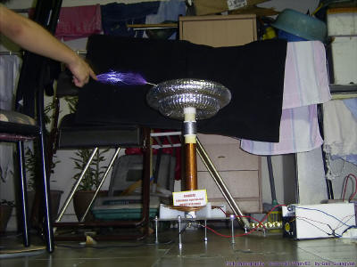
Trick photography. This is two photo
overlaid over each other.. about 18cm arcs.
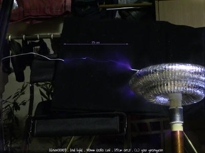
Highlight of the day! My coil has reached
25cm!
The improvements have
significantly improved spark length and overall, the coil is
much louder.
Download Video clip of 18cm arcs:
tesla_2light.wmv (558kb)
The arcs are very thin... notice the safety gap
firing in the first part of the video as a very bright light.
Today's maximum arc length from breakout
point to RF ground : 25cm |
24th Nov 2003 (Monday)
|
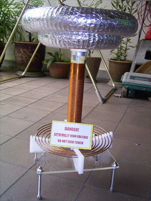
Some parts of the coil have been slightly
changed and the spark gap has got a new fan!
The toroids have been shifted down to
remove the secondary corona, and the top part of the secondary
has been slightly varnished (the shinier part) just in case.
Looking good.. :-)

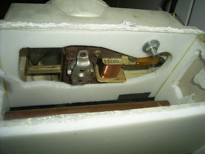
There's the new spark gap! The fan is from
a microwave oven. It's powered directly from the mains and is
very powerful. My previous two computer fans mysteriously
died. Anyway, I needed a step down transformer and a bridge
rectifier to power those CPU fans.. it's much easier and
tidier now. The original fan casing was kept (but was sawed to
fit). A large hole was cut at the side of the gap. You can see
it in the second picture (through the clear acrylic bottom
plate). The fan is connected by a large bolt, friction, hot
glue, silicone sealant and a touch of duct tape to complete
it. The original fan holes were covered with duct tape..
simple but effective. The fan roars now. :-) I am hoping this
would improve things a fair bit.. took around 1hr to make all
the changes with the gap and the secondary setup.
later on at night...
The varnish and silicone has dried. Time to
fire it up. (click pictures to enlarge)
The added fan HAS indeed improved spark
brightness and thickness quite a lot! But there is no
significant spark length improvement. The coil now runs much
louder and fiercer. The noisy fan is completed drowned out by
the spark gap.

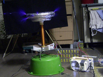
Compare this to the photos above. The are
much brighter and powerful. The connected streamer on the
right is 25cm And
here are the best shots of the day...
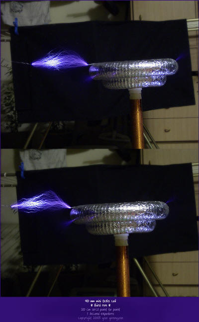
Much thicker arcs! 20cm. There really is a
difference!
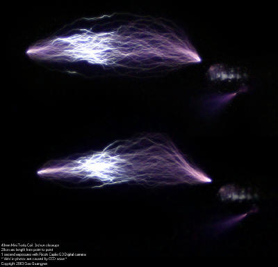
These are really beautiful. Again 20cm
length, but the camera is much closer now.
However, there is still no 'real' large
streamer. I think my toroid is too rough, preventing breakout.
I shall try to smoothened it and see how it all works out. The
new spark gap has really made a lot of difference I am am
pleased with the new results. I still want to improve spark
length and I shall see if I can get it up to 40cm.
Everything's still holding up fine. Ozone smells terrible..
Today's maximum arc length from breakout
point to RF ground : 27cm |
|
Due to
extremely tight schedules since the beginning of this year
(2004), I am unable to do more work on this coil. More work
will resume however. [ 28th July 04 ] |
|
8th August 2004
 Tomorrow
is Singapore's 39th National Day! Due to that, there are 2
free days as holidays. (Actually, I can't really call school
holidays 'holidays' anymore because we are given stockpiles of
work which is extremely stressful and pressurizing. School is
definitely not helping the progress of this project! In any
case, work must go on, and thus I have decided to tweak
up the coil. Tomorrow
is Singapore's 39th National Day! Due to that, there are 2
free days as holidays. (Actually, I can't really call school
holidays 'holidays' anymore because we are given stockpiles of
work which is extremely stressful and pressurizing. School is
definitely not helping the progress of this project! In any
case, work must go on, and thus I have decided to tweak
up the coil. I am
still not happy with the performance of my coil. After looking
over my coil design, I found a possible source of problem -
the spark gap. Although I believe it has great quenching power
(from the powerful fan), the problem was that the copper tubes
were connected to the wiring via steel wire and steel threaded
rods. Steel has a high electrical resistance compared to
copper or brass, and other coilers have reported instances
where steel connections heated up a lot. As such, I decided to
dismantle the spark gap and build a new static spark gap. In
the picture you can see the eroded copper pipes. I sanded the
whole pipe down so it was shiny again. The new gap will use
much less copper though...

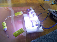
And there you have it, the new adjustable
static spark gap. It consists of 3 fixed copper rings screwed
down to a HDPE stand. There is one adjustable brass machine
screw as the last electrode. Termination electrodes are all
brass. Although this can't handle as much power as the first
big one, it's much smaller and this time, no steel! I'll
probably add a powerful fan blowing across the gap to assist
in quenching as well as to prevent it from over heating. It's
probably not the nicest looking gap, but it seems to work
great. In the second picture, you can see the gap firing from
caps charged with my flyback. I am hoping at 225W of power,
the gap won't overheat too quick though, otherwise I will have
to make a new one. I'll probably build a stand to encase all
the components too. Hopefully I can find more time. |
|
9th - 10th August 2004

9th August: I built a
wooden stand, with 2 decks (2nd deck supported at one side and
one edge, but still strong). I also cleaned up the dusty
capacitor bank and changed the output lugs to thinner wire.
Why thinner wire? The previous thick wire was too think and
soldering was impossible. Now, although the wire is thinner,
the connection is much better (soldering is possible now).
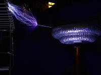
When I powered the coil
up, it worked for a while, then it stopped. Analysis revealed
that the 15kV 30mA transformer was now fully dead! (Was half
spoilt at first, so I was using the other half, 7.5kV 30mA.
I'm not sure what's wrong as the whole transformer is resin
potted, and thus I cannot dismantle it. Unhappy with the loss
of my 225W unit, I decided to plug my dual MOT power supply
supplying 12kV DC pulses to the coil. Even though I did not
tune it or adjust the spark gap, there was significant arc
length improvement and ground arcs were much thicker. This is
evident in the photos below. I need to get a new NST to power
my coil. My friend, known as raptor, happens to have a
6kV 30mA NST lying around and he is willing to trade with me
it for an amount of magnet wire. Although it's only 180W this
time, I have no other choice... I will be going to his house
to collect it tomorrow.


 10th
August 10th
August
Today I got the 6kV 30mA
NST from my friend. The NST is the type which is in a metal
container, potted with a black substance (probably tar). It's
by Standard Electric Works (Hong Kong), and the date says Sep
86 on it. Though a bit rusty, it works perfectly! It's a
center tapped unit.
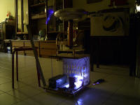
I completed the wooden
stand today. The NST is the green box with a black sticker on
it, and weighs around 4 - 4.5kg. I bought 4 plastic wheels
(cost $5) and screwed them on the bottom to increase
portability.

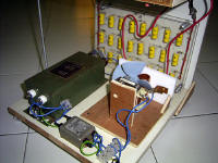
I also built a bigger,
more durable spark gap. As you can see, there are 3 2inch long
copper pipes bolted to a HDPE board, and a 6mm brass bolt at
the end of the last pipe to make it adjustable. All
connections are now copper or brass, no more steel. I also
have a rather powerful fan blowing right on it, so quenching
should be ok. Everything including a 3A EMI filter is attached
on the stand.
 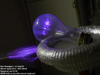
On the right, you can
see the coil running. Performance is ok, though I'm still
unhappy with the spark length. Notice the nice streamers
inside the large 300W light bulb. There is one more thing to
try.. that to the increase the height of the primary to
increase coupling.
I hope to do that soon,
and the coil will be more or less complete! |
|
13-14 August 2004
 Time
to fix the primary. Time
to fix the primary.

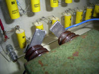
I cut out 4 6mm x 100mm
x 30mm Acrylic pieces, and drilled two holes at the top 1cm.
These are then tap screwed into the HDPE primary supports,
effectively raising the primary coil by 2 cm to improve
coupling. The hot glue and other stuff were scraped away
(albeit leaving many marks on the acrylic base), and the
supports were glued to it using Chloroform (trichloromethane)
which is like a solvent for acrylic, allowing it to bond
chemically. The second picture shows the aluminum spark gap.
Also, you might have
realized that I have removed the larger toroid from the coil.
I tried with the small one only, and arcs seem best at turn
4.5 to 5. Streamers are now longer! (Primary would be tapped
at turn 5.75 for the large one and the small one together).
More test and arc photos will be taken tomorrow. I hope to
improve spark length even further! |
|
14 Aug 2004
I powered up to coil today. Primary is
tapped at turn 5. I did something different: Since the coil is
now running inside my house (instead of in the backyard), I
can't get a proper RF ground without running a very long wire.
As such, I connected the bottom of the secondary winding to
the first turn of the primary. This configuration is similar
to an Oudin coil/resonator. Although this configuration
eliminates the need for a RF ground, and also eliminates the
possibility of a primary or secondary strike, it injects
dangerous primary AC currents into the output streamers.
Performance is most satisfactory! I guess it works without
much loss in a small coil like this one.


The first photo shows the coil in action
with a metal rod (stuck on a wooden pole of course) drawing
arcs off it. The second photo is a long exposure (a lot of
digital noise) of the coil in action, and the last photo is
the coil with a breakout point.
The photo on the left is
probably the best photo of the coil actually producing
streamers. Performance has indeed increased! Note that without
the larger toroid, there are even more streamers. I
hypothesize that the toroid is either too small, or it is too
rough. For the time being, I'll stick with this.
Today's maximum arc
length to ground is 25cm, and that's which 180W. Previously at
225W, maximum arc length was only 27cm. I am rather happy with
the results, but I still hope to improve them. |
|
21st August 2004
 If
you read about my 729J single stage coil gun (schcoil04)
I did for my school's research project, you will know about my
project mentor, A/P A. Kursheed from the National University
of Singapore (NUS). After hearing about my Tesla coil, he was
extremely interested. Since I had just completed fixing it
together in a nice base, I decided to inform him about my
Tesla coil. He wanted me to bring it down to his lab, which
was exactly what happened today. In the photo on the left, you
can see the coil in his lab. If
you read about my 729J single stage coil gun (schcoil04)
I did for my school's research project, you will know about my
project mentor, A/P A. Kursheed from the National University
of Singapore (NUS). After hearing about my Tesla coil, he was
extremely interested. Since I had just completed fixing it
together in a nice base, I decided to inform him about my
Tesla coil. He wanted me to bring it down to his lab, which
was exactly what happened today. In the photo on the left, you
can see the coil in his lab.
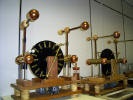
  There
were some really large and well built Whimshurst generators
(motorized), with very good performance. There was also a
commercially made tesla coil at the lab. Notice how tall the
secondary is. The wire used to wind it was really thick.
Although the construction was rather good, performance was
actually worse than my own coil! The last photo shows the Mica
transmitting capacitors with a multiple tungsten static gap.
My mentor was very pleased with the performance of my coil,
and he wanted to keep the coil for maybe a few weeks to show
his students. I will collect it back soon. He might also want
me to talk and advise his students on this area. There
were some really large and well built Whimshurst generators
(motorized), with very good performance. There was also a
commercially made tesla coil at the lab. Notice how tall the
secondary is. The wire used to wind it was really thick.
Although the construction was rather good, performance was
actually worse than my own coil! The last photo shows the Mica
transmitting capacitors with a multiple tungsten static gap.
My mentor was very pleased with the performance of my coil,
and he wanted to keep the coil for maybe a few weeks to show
his students. I will collect it back soon. He might also want
me to talk and advise his students on this area. |
Gao Guangyan
Extremely dangerous: Do not try at home.
I am not responsible for anything that happens should you attempt
such a project.
Last updated: 12 Aug 2004/ 28 July 2004 |

