loneoceans labs | IGBT Brick Driver (temporary placeholder page)
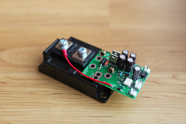
BrickDriver v1.0 mounted on a CM300 single IGBT module
BrickDriver is a straightforward no-frills Discrete Opto-isolated Gate Driver designed to drive large IGBT modules - affectionately known as 'Bricks' due to their large size, weight and shape. BrickDriver takes in an isolated 3.3V/5V TTL/CMOS logic input, and drives the largest IGBT (or MOSFET) modules via a +15V and -8V gate drive, with active miller clamping, desaturation detection and isolated fault sensing.
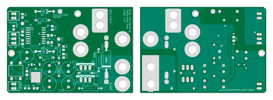
BrickDriver is compact. One of its key features is its very versatile footprint - it was designed specifically to mount directly on many single-switch IGBT modules such as the single-switch Powerex, Semikron and Mitsubishi CM300/400/450/600 modules, as shown above. I originally designed this board specifically for driving large IGBTs in my projects, specifically for a large 200A buck converter in my QCW 1.5 Tesla Coil. However this driver has since been used in many other instances where a discrete isolated and robust gate driver is required. Due to popular demand, I am now offering these for sale.
![]()
The
BrickDriver system including design, schematics and layout are available above
under the Creative
Commons License.
What does this board do?
This board is a single-board IGBT / MOSFET gate drive solution implementing a high-current driver (via buffering FETs / BJTs) via industry standard opto-isolated gate drivers, specifically the Avago HCPL-316J and the Fairchild FOD 8316 2.5A driver ICs (these are identical pin-compatible drivers). The board buffers the output with large TO-220 complementary transistors of your choice for >15A gate drive capability, and is robust enough to drive even the largest 1000A IGBTs (or MOSFETs). The board also includes an on-board split-rail power supply offering +15 and -8V gate drive voltages, as well as desaturation detection, configurable Rg_on and Rg_off resistors and gate TVS.
The result is a simple and effective isolated gate driver board suitable for a wide range general-purpose uses, and has been one of the most useful boards I've made. Note that this board was not designed for the purpose of driving the bridge for use in a DRSSTC inverter - for that application, please see the UD2.7 driver, which works best paired with a properly designed gate drive transformer. Instead, this driver excels as stand-alone discrete driver used in power switching transistors such those used in large buck/boost and other power converters.
The BrickDriver has the following features:

Sept 2017 - Version v1.1
- Small modifications to silkscreen, layout, and copper pours for
better performance and IGBT alignment
- Added 24VDC input jack for use with isolated 24VDC
switching supply instead of heavy iron-core transformer
- Shifted and changed bridge rectifier; adjusted component
designators
Nov 2014 - Version v1.0
- See here for V1.0 layout
- See here for V1.0
schematic
For more implementation details, please see: HCPL-316J-000E or FOD8318 Opto-isolated Gate Driver datasheets.
These boards are currently being offered for sale as a bare PCB board. Operation should be very straightforward and covered comprehensively in the Avago or Fairchild datasheets.
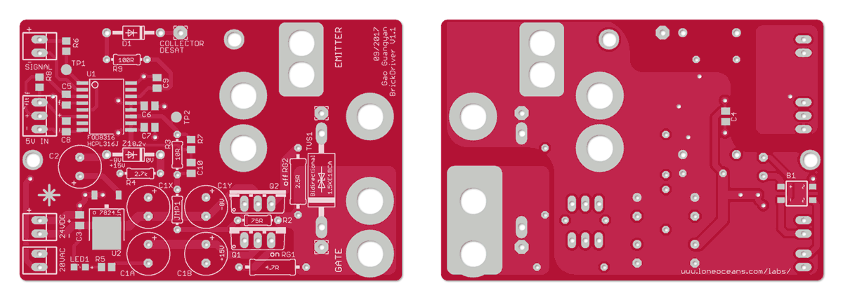
The listed prices are for a single blank board measuring about 7.5 x 5cm in size. Board design pictured above.
If the boards are sold out, please check this page periodically. I'll be updating this page if there is more in stock. This board was designed as a personal project and may not work with your set-up.
Please note this board was designed solely as a personal hobby board, and interfaces with potentially deadly mains / line voltages and high power circuits! I make no claims that the board satisfies any UL, CE or any electrical standards. You will bear all responsibility for using this board correctly and safely in your project with good engineering practices. Note that I will NOT be able to provide technical support, other than questions about the physical board itself. For usage instructions, please refer to the datasheets of the specific drive ICs you use.
Shipping and handling is from the USA to anywhere around the world, starting at $4.50 for USPS regular mail and starting at ~$18.50 for international orders. All prices are in USD and subject to change.
Contact loneoceans [at] g mail [dot] com for enquiries.
Bill of materials including schematics to aid in board assembly and debugging are as follows.
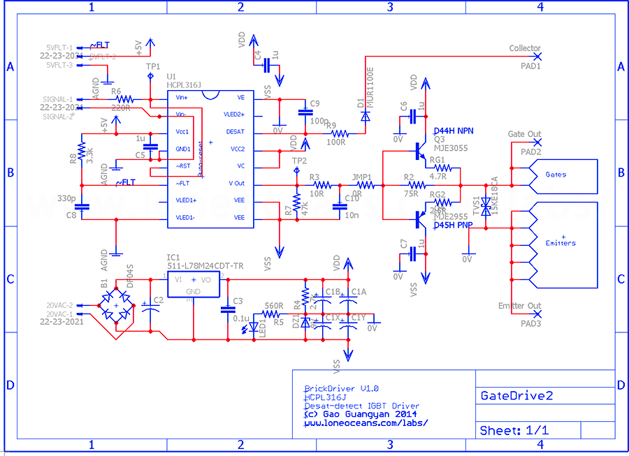
Schematic
![]() Details
for the BrickDriver including design, schematics and layout are available above
under the Creative
Commons License.
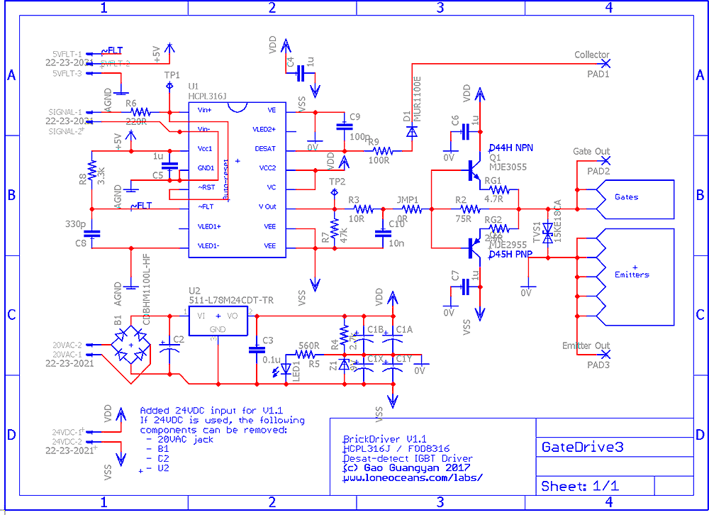
Above shows schematic for v1.1. Please see the Revision History section above for older rev. details and
schematics.
Details
for the BrickDriver including design, schematics and layout are available above
under the Creative
Commons License.
Above shows schematic for v1.1. Please see the Revision History section above for older rev. details and
schematics.
Bill of Materials for v1.1
The parts list for the BrickDriver is as follows and should be available on
popular sites like Farnell, RS, Mouser or Digikey.
Some exact part numbers are shown, but you can substitute for similar components
if desired.
Note that the driver can be powered either with a ~20VAC transformer, or via an
isolated 24VDC supply. If the 24VDC supply is used, please
do not populate B1, C2 and U2.
Additional parts:
The board has been designed to be easy to solder and assemble together by hand.
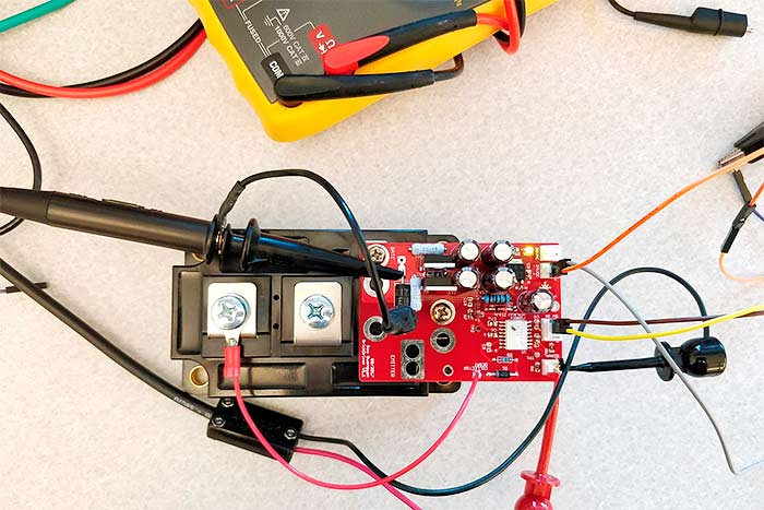
Above shows a photo of BrickDriver V1.1 during testing.
Board Verification & Usage
First, plug in 24VDC or 20VAC into the power input (this needs to be isolated, i.e. from a regular iron transformer or isolated SMPS, up to the bridge bus voltage especially if it's the driver for the high side switch in a half of H Bridge for example). LED1 should light up and indicate the gate drive rail power is on. Measure VDD and VSS w.r.t. 0V rail (see schematic for where to measure at). V_vss_0v should be about 8.2V, and V_0v_vdd should measure around 15.8V. If this is right, your power rails are as expected. In practice depending on the load, this split rail voltage may measure closer to -7.2V and +16.6V for example.
Second, connect the 5V power at the 3-pin connector (remember this needs to be isolated from the gate drive rail) from an external source (typically from a micro-controller or similar) to the BrickDriver board. Note that desaturation detection turns the driver into a fault state when V_desat - V_emitter > 7V (where the driver then executes a 'soft' turn off and holds the driver LOW). Hence for testing, connect the Collector terminal to the Emitter for now. Alternatively, connect this to an actual IGBT making sure the Collector is also connected.
Also note that the ~FLT (fault) pin can be left unconnected if not used, or connected to your microcontroller. Note that the BrickDriver is configured for auto-reset during a fault condition. Modify if necessary (see relevant datasheets for the opto-driver IC).
To verify proper operation, scope the outputs of the gate drive with an oscilloscope probe connected such that the ground is to the 'Emitter' and the probe is to the 'Gate'. When ready to measure, send the gate drive logic signal to the Signal input. When a logic HIGH is applied to Vin+, the Gate voltage should show +15V or so on the scope. When a logic LOW is applied to Vin+, the gate voltage should be -8V. This pin (Vin+) cannot be left floating. If this is seen, the driver is working. The gate resistors can be adjusted to suit your needs for your desired gate turn ON and turn OFF speeds.
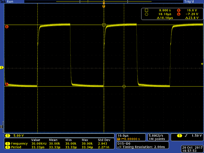
Above is an example of what you should see. The probe is measuring the gate-emitter voltage w.r.t. emitter. The BrickDriver is connected to a large CM300HA-24H IGBT and the desat-detect terminal connected to the collector of the IGBT. 24VDC is fed to the driver. In this case you can see that the split rail supply is producing +16.6/-7.2V gate drive voltages. A +5V/0V square wave at 50% duty cycle at 30kHz is fed into Vin+ from a signal generator. The result shows proper operation. Note the tiny plateau during the rising gate-drive edge hovering just under 10V. This is the Miller Plateau (see page 6 of this app. note). Brick driver has been tested from 0Hz all the way up to 200kHz and works just fine - however typical large IGBT operation usually does not exceed ~30kHz or so. Note that the Brick Driver can also drive large brick-type MOSFETs.
Finally, note that you can also configure the gate drive voltage levels by changing Z1 which sets the negative gate drive voltage, as well as adjusting the input voltage for the main gate drive supply. Ensure also that these are within ratings for the buffer transistors, gate drive IC, as well as other passives.
Please see HCPL-316J-000E or FOD8318 for more technical details on their operation.
===
For more enquires, please contact me at loneoceans [at] gmail [dot] com.
Back to loneoceans labs. (Updated May 2020)