pogoProg - small spring-contact programming header tool
Introduction
Over the past year or so, I've been working on a series of fairly small
flashlight LED drivers, which incorporate a bunch of features on a very
small PCB. One such example is my GXB172 driver,
which is a diminutive 17mm diameter in size, but has an Atmel/Microchip
ATtiny841 microcontroller on board.
These Atmel microcontrollers can be flashed in a variety of ways, but
one of the most common ways is to use In-System-Programming (ISP),
commonly done with Atmel's own AVR ISP 2 programmer, or the newer
Microchip/Atmel ICE programmer. Among others, there are a variety of
cheaper AVR ISP clone devices including AVR USB programmer.
These programmers typically use a standard 2 x 3 100-mil header for
programming. Unfortunately this takes up too much space on my PCBs, so
I've reduced the size of the 6 required pins to be 2 x 3 50-mil pads
instead. I built the pogoProg tool as a simple way to program these
microcontrollers.
You can build your own using the PCB files provided and
component list! For more information, scroll below :)
Feature List (of pogoProg+)

- Designed for 2x3 50mil-space pads for AVR ISP
programming
- Uses 6 pogo-pins for programming
- Connects to AVR ISP / AVR USB / ATMEL ICE via standard 6-pin
100mil header
- Allows external micro-usb for 5V or 3.3V power (selectable via
on-board switch) to VCC
- On-board poly-fuse for protection against VCC shorts
 In
this page, I'll outline the motivations of this project, how I designed
this driver, and how I put them all together. Hopefully this will also
be a useful resource for many like-minded hobbyists around the world :-).
The pogoProg and pogoProg+ designs including schematics, layout,
firmware, and architecture are available freely on this page under the
Creative
Commons License. In
this page, I'll outline the motivations of this project, how I designed
this driver, and how I put them all together. Hopefully this will also
be a useful resource for many like-minded hobbyists around the world :-).
The pogoProg and pogoProg+ designs including schematics, layout,
firmware, and architecture are available freely on this page under the
Creative
Commons License.
Jan 2018
pogoProg Development
Development History
An older way I used to program Atmel MCUs on small PCBs.
Previously I used a fairly inelegant method
to program my target MCUs suing the same 2x3 50-mil pads, but had to
solder connectors or wires to it to program. This was fine for 1-off
programming uses, but modifying code was complicated.


Above: various kinds of pogo-pin-based programmers such as from
Tag-Connect, and other generic 3rd party ones
Common in the EE industry is the use of
simple pogo-pins for programming, such as the ones pictured above. So I
decided to make my own instead. The tricky part was mounting the
pogo-pins correctly in the right spacing, but I found that if I made the
PCB out of 0.8mm thickness FR-4 (a fairly common thickness), they would
essentially fit 50-mil spacing pads easily.
pogoProg
The basic pogoProg is essentially an interposer board
allowing you to connect your programmer to the target microcontroller.
It features an on-board LED as well which lights up when VCC is powered.

Above shows the completed pogoProg after assembly. This
tool does not supply power to VCC, so the target MCU needs to be powered
by some external power supply.
Board Files and BOM
The PCB can be ordered
here via
OSHpark. Be sure to select the 0.8mm thickness 2oz copper option.
Pins required - 6x P13-0123 (Harwin, expensive) or
P50B1 (on Aliexpress or eBay for cheap)
D1 - 0805 LED of your choice, I recommend Orange or Red
R1 - 0805 Resistor of your choice, I recommend something like 1kR
Header - 0.1" (100mil) 2 x 3 Rectangular header
I recommend building the pogoProg+ (below) instead of
the standard pogoProg for more versatility.
pogoProg+
The pogoProg+ builds on the pogoProg and adds a few
features, including a 3.3V voltage regulator for 3.3V programming, as
well as a micro-USB header for supplying power to the VCC pin to allow
the MCU to be powered without external power source. For safety, a
poly-fuse is added in case of VCC - GND shorts.

Two small switches on board allow power to the VCC pin
be turned on or off, and for VCC voltage to be toggled between 5V and
3.3V.
Schematic

The pogoProg and pogoProg+ design including schematics, layout, firmware,
and architecture are available freely here under the
Creative Commons License.
Above shows the schematic for the pogoProg+.
Board Files and BOM
You can order your own pogoProg+ here via OSHpark.

Be sure to order the board in 0.8mm thickness with 2oz
copper. The 0.8mm thickness is required for correct pin-spacing.
PogoProg+ Rev A - Bill of Materials
Pins - Harwin P13-0123 or
P50-B1 x 6 (whichever cheaper, pins for cheap on Aliexpress / ebay)
Switches - CAS-220TB x 2
Regulator - AP2114H-3.3TRG1 x 1 (3.3V regulator)
USB - Molex 1050170001 x 1
F1 - 0ZCK0100FF2E x 1 (1A PTC Poly-Fuse)
C1, C2 - 4.7u 0805 Capacitor CL21A475KAQNNNE x 2
D1 - 0805 LED of your choice x 1 (Red or Yellow is good for lower
voltages)
R1 - 1k 0805 Resistor x 1
Header - 2x3 100mil - to AVR ISP 2 or Atmel ICE x 1
Components are available on Digikey or Mouser. If
unavailable, feel free to substitute for a similar part.
Using the pogoProg
PCB Design - Pinout
Below is the recommended layout pattern for the pogoProg
as well as the associated pinout.

Designator Recommended Min
Recommended
Comments
A
25mil / 0.635mm 30mil / 0.762mm
Make larger if applicable
B
0mil
11.811mil / 0.3mm Must be smaller than 0.4mm else pin
will go through
C
50mil / 1.27mm 50mil / 1.27mm
Do not change
D
25mil / 0.635mm 28mil / 0.711mm
Make larger if applicable
These can be copper pads or vias. The square pad
designates pin 1, but it can be in any shape you like. It is recommended
for pin 1 and pin 6 to be vias for easier registration of the pogoprog,
but these are not required. The via drill should not exceed 0.4mm to
ensure the 0.5mm pin does not go through.

Above shows an example layout of the pads for use with
the pogoProg, showing the 50-mil spacing. Noticed that only the GND pad
has drill for registration. Any of the pads can have a drill/via added
on for easier registration. The recommended drill size is 0.3mm, or
10-12 mil.
Connecting the pogoProg
The pogoProg and pogoProg+ has a 2x3 100mil header for
interface with off-the-shelf programmers including the now discontinued
AVR ISP 2 (but many clones still exist), the new Atmel ICE, and other
USB AVR ASP programmers. The pinout of these programmers are the same as
the pads for pogoProg, with MISO being pin-1.

Above shows how the pogoProg can be connected to the
Atmel ICE using the 6-pin header on the AVR cable side.

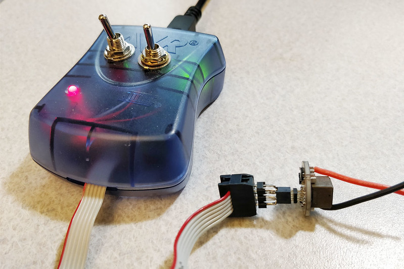
And above here shows how the pogoProg is connected to
the Atmel AVR ISP2 programmer. Note that this programmer is one that I
modified myself to supply power to the VCC rail (usually VCC needs to be
powered externally), and I found this feature very useful. As a result,
this feature was replicated on the pogoProg+!
Using the pogoProg to Program
Using the pogoProg is fairly straightforward. Let's take
a look at an example target - my GXB172 driver PCB.

Above we can see the 6-pads corresponding to VCC, MOSI,
GND, MISO, SCK and /RST. After the microcontroller is soldered on, the
progoProg is aligned carefully.

Using the pogoProg+ to program the microcontroller on my small
GXB17 LED flashlight driver
Above is another example using the progoProg+ to connect
to the target physically.
Note - it is very important to verify
that the programmer is in full contact with all pins. When programming,
keep movement as little as possible. Breaking the connection when the
device is in the process of being programmed can cause the target MCU to
be stuck in a debug mode, which may required high voltage programming to
un-brick! When programming, I usually use Atmel Studio 7.0 (free to
download from Atmel's website) >> Tools >> Device programming. I verify
that the device ID can be read first. Once this happens, there is good
contact and programming can begin.
Back to main page
(c) Gao Guangyan 2026
Contact: loneoceans [at] gmail [dot] com |
