
PCB Layout for SSTC 4 v1.0.
loneoceans labs | SSTC 4 PCBs (temporary placeholder page)
PCB Layout for SSTC 4 v1.0.
 The SSTC 4 single-PCB Tesla Coil was developed as a
full-featured all-purpose Solid State Tesla Coil platform for building a compact
yet powerful full-bridge coil, all on a single PCB!
The SSTC 4 single-PCB Tesla Coil was developed as a
full-featured all-purpose Solid State Tesla Coil platform for building a compact
yet powerful full-bridge coil, all on a single PCB!
This revision was developed as an improvement over my SSTC 3 half-bridge platform, and builds upon it with many improvements. Full-bridge operation allows significantly more power output compared to a half-bridge. The SSTC 4 platform was designed primarily to be run from the sine-wave ramp from the mains ('ramped mode'), but can be easily converted to regular SSTC operation with the addition of a bus cap, and also into a DRSSTC with the addition of a tank capacitor. The board was designed to be easy to hand-solder.
Some SSTC4 standout features include:
SSTC 4 was also designed with a demo simple daughter interrupter board which features staccato mode via an ATtiny Microcontroller (instead of a bunch of discrete components) as well as an on-board ST-Fiber receiver for use with your favourite optical interrupter controller.
Current latest version - v1.1 (March 2016).
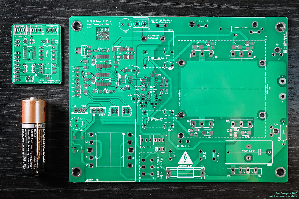
I sent a small batch of PCBs for this coil project and had several leftovers. Due to popular demand, I decided to offer them for sale. These boards should be an excellent starting point for more advanced SSTC hobbyists. Below shows the front and back of the main PCB as well as the demo controller board.

This set comes with the following items I developed specifically for this project:
Because this set is a development board set, I will not be able to provide additional support for you to use the boards, and you should have a good amount of experience in SSTCs. This is an advanced project. For more information, you can see my SSTC 2, SSTC 3 and SSTC 4 pages for a comprehensive write-up on how I used them including schematics and more. Operation should be fairly straightforward for the experience coiler.
Pricing
I'm offering a SET of two boards for sale for US$65. This includes the following:
- One unpopulated SSTC 4
v1.1 PCB. Comes in standard green HASL finish and
has been
electrically tested at the fabrication plant
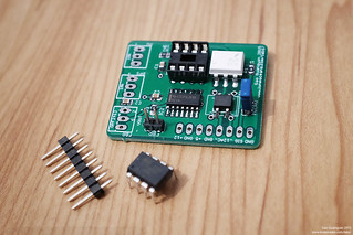
- Populated, assembled and programmed demo controller board as pictured above.
You will need to supply your own potentiometers and molex headers if desired. See below for more info.
This set should allow you to get started quickly!
Current Stock - Latest version v1.1 boards. All SSTC 4 boards are now sold out. Replacement interrupter modules still available for $20 each. No planned future orders once completely sold out! (July 2016)
Shipping to anywhere in the US will be via USPS Priority Flat Rate for
US$7.50.
Will also ship to anywhere around
the world. Contact loneoceans [at] g mail
[dot] com for enquiries.
For more information of usage including schematics, please see my
SSTC 4 page.
Many of the parts used are quite generic (e.g. various resistors, bypass capacitors). This list is broken down into a few sections with associated Mouser.com part numbers. Feel free to change the components to suit your needs. Components should also be easily available on Digikey, Farnell, Element14, RS electronics etc.
Power Supply
Power Electronics
Logic and Gate Drive
Shared / Common Parts
Connectors, Headers and Switches
There is a single errata on the SSTC 4 v1.0 boards, requiring the addition of a single extra 20k resistor. Version v1.1 onwards fixes this with a new 0805 resistor placement.

A regular 20k resistor (R16) can be easily soldered in the existing vias of R9 and R14. The original board missed out this resistor, which led to the coil having difficulty in starting oscillation. The addition of the resistor generates an initial 'pulse' from the interrupter signal, which initiates a feedback pulse. Thereafter, the usual feedback signal takes over. This fix applies for v1.0 boards only.
SSTC 4 was designed to run a variety of effects, but primarily to be run in ramped-mode like SSTC 3. A demo interrupter was made as a quick start. In order to reduce parts count, the analog staccato interrupter has been updated to use only an optocoupler + a small Atmel microcontroller (ATtiny45/85). SSTC 4's interrupter input has the same pin-out as SSTC 3 for compatibility.
Note the 8-pin 0.1" pitch male headers should be installed on the opposite side of the board to plug into the main board. All components are labeled and can be populated as follows in the schematic. This board allows for both staccato operation as well as optical input via a standard ST OPF2412 optical receiver, and can be used with say a MIDI optical controller like I use on my DRSSTC coils. Operation is selected via the 2-pin headers, where only one (either FBR or MICRO) be jumped with a jumper at any time.


All resistors and capacitors are SMD 0805 size. The pin-out for the 8-pin board interconnect is as follows:
PW and BPS should be connected to external 10k potentiometers. Standard 0.1"
pitch molex headers can be used. The hobbyist is encouraged to experiment with your own
interrupters. :-)
Assembled and programmed boards for sale DO NOT include potentiometers
- you will need to supply your own 10k pots (x2), headers (if desired), as well
as your own fiber optic receiver if desired.
Additional Bill of Materials for demo controller
For more information including .HEX code for the microcontroller, please see my SSTC 4 page.
SSTC 4 can be converted into DRSSTC operation. To do this, the small 1/1.5uF cap (C12) should be replaced with a larger bus capacitor (e.g. a 18mm x 7.5mmLS 400V 220uF capacitor), with some extra external bus capacitance (e.g. 1000uF 400V with an external cap). This can be connected via V+ and V- input jacks on the right-edge of the board. Keep the leads as short as possible (and twist wires together) to minimize bus inductance. Alternatively, foot-prints for C15A can be used as well.
Next, C11 should be replaced with the resonant tank capacitor, which can be off-board. This will depend on your primary configuration and coil geometry.
Primary feedback can be used by installing CST206-1A (100 turns) or similar 200 and 300 turn transformers (2A and 3A models).
Finally, ensure the correct interrupter is used for DRSSTC operation, which will require much shorter-pulse widths. Alternatively the demo interrupter card can be used with fiber input from a regular DRSSTC controller.
This section showcases some of the builds I have received from hobbyists who wanted to share what they have built with the SSTC 4 platform! Photos below are by their creators and reproduced here with permission.
Coilfan's Ramped DRSSTC

Above shows Coilfan's coil which he has named the 'Baking Pan' coil, characterized by the interestingly shaped topload, and reproduced here with his permission. So far he has managed to get some really excellent performance up to 25 inches long using the SSTC 4 board and the demo staccato interrupter. The coil has been configured for double resonant operation. Very impressive performance and really shows what the SSTC 4 platform is capable of.
Stanislas' SSTC 4

Stanislas created a very well performing coil with the SSTC 4 board using 60N60 IGBTs and operating in SSTC mode with 230VAC and at roughly 350kHz and secondary current feedback. The result is some surprisingly large sparks! Above shows the progress of his coil and some photos of the build in progress.
Thanks for sharing and great job with the builds!
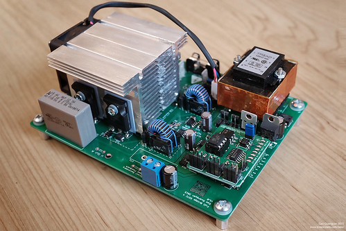
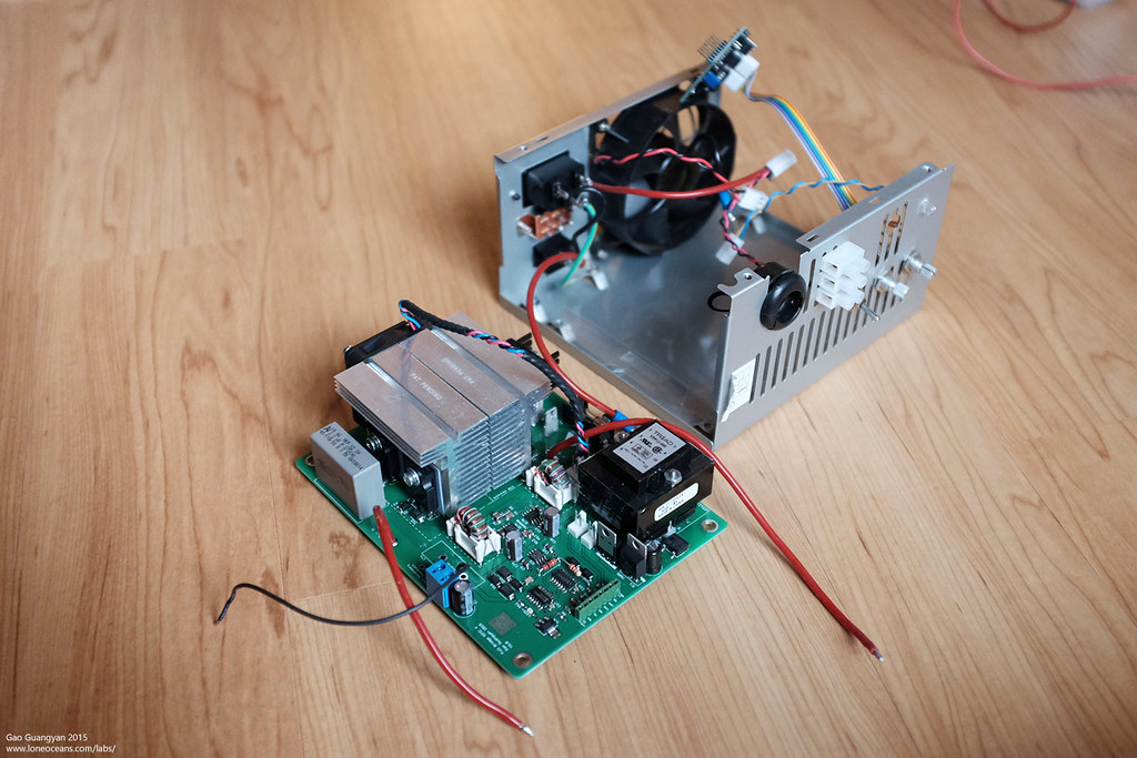
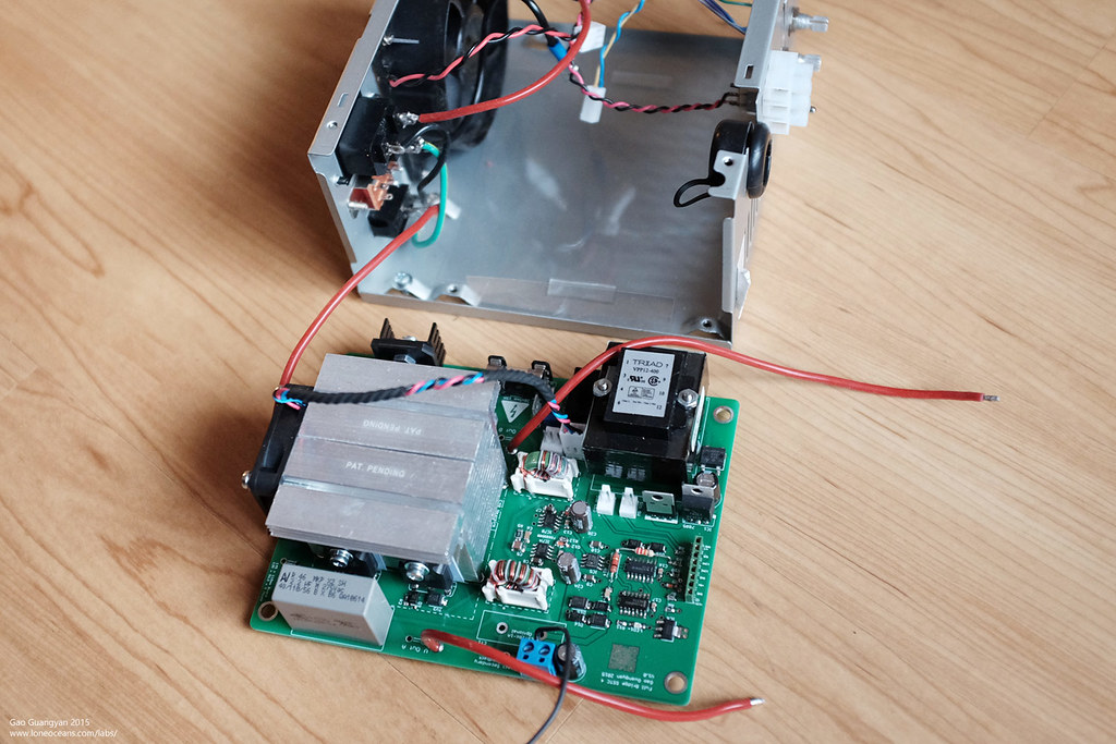
For reference, here is a SSTC 4 V1.0 board populated and installed in an ATX power supply case. Note the small heat-sink installed on B2 bridge rectifier, as well as the interrupter connected to two 10k pots mounted on the case. A single switch and a LED provides signal indication. The setup as shown below was designed to be running as a ramped-SSTC and therefore only uses a small 1uF film cap as the 'bus cap'. Also visible is the errata resistor R16 as described above. Finally, note that this coil uses direct secondary feedback. It is also possible to use a secondary CT, or a primary CT (in DRSSTC mode) for feedback.
Please see my SSTC 4
page for more details of my build with this coil. Looking forward to seeing what
you can come up with this board!
Back to loneoceans labs. (Updated July 2016)