About a year ago in the start of 2017, I embarked on a series of small power electronics
projects - compact and high-power boost drivers for LED flashlights.
These LED drivers enabled multi-die 6V or 12V LEDs to be driven from
single-cell lithium
batteries (such as 18650s), at very high power levels. These projects started with the GXB20
(Rev 1 and Rev 2), and then the GXB17. These
flashlight drivers turned out to be
quite successful and the results allowed me to build some small but very
bright flashlights, exceeding the brightest flashlights on the market in
their size category (at time of design in early 2017).
As I started going a little deeper into the rabbit-hole, I
soon found myself asking the question - could I make these small flashlights
even
brighter? This was the motivation for the GXB172 project.
The idea was partly a
just-for-fun project to see how bright I could make a compact flashlight
be, though more importantly, I saw this undertaking as a fun intellectual
engineering challenge, and as
an excuse to play around with some small form-factor power electronics.
This was
a breath of fresh air compared to some of the big power
electronics I've been working on for my Solid State Tesla Coils (see the
rest of my website for more on those).
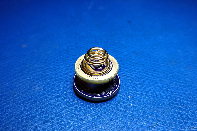
Above - the completed and working GXB172 Rev A2 - a 50W constant-current
single-cell programmable LED driver
This page outlines the design and creation of what I hope will be
probably
the world's most powerful small size 17mm single-cell flashlight boost driver (at
time of design early 2018, at least). I've done my best to try to
document this project as it goes along, and hopefully other hobbyists
will be able to build their own GXB172 driver, as well as build upon it
to make it even better.
Finally, a caveat - practically speaking, this driver
doesn't make much sense! Driving an LED at 50W necessarily leads to
significant thermal heating, which in a small flashlight (where a 17mm
driver is needed!), is physically unable to sink for any more than
several 10s of seconds to a minute, and thermal overload will necessary
occur. We can't beat physics here!
As a result, it would make more
practical sense (if such a power handling capability is desired) to use a physically larger flashlight, where one could
then use larger or more cells, and a larger driver, thus negating the
need for the existence of the GXB172 driver! However, I worked on this project
purely as a for-fun endeavor. The result was a project which I
learned a lot from, and allowed me to build some pretty powerful
flashlight (albeit before they get too hot), and still enables the use
of some very nice multi-die LEDs in a small form factor. So I suppose
there is at least some value. :-)
The GXB172 Feature List & Downloads
What is the GXB172?
The GBX172 is the 2nd version of my
17mm form-factor boost-type LED Flashlight driver, capable of 50W, hence
the addition of the 2. It uses a completely different control topology
from the GXB17, as well as different power components.
A year ago in 2017, I developed the
GXB17 and GXB20 flashlight
drivers. These were simple constant-current single-cell, programmable,
boost LED drivers, made specifically to run multi-die 6V or 12V LEDs at
high power levels, around 20W. The new GXB172 builds
upon the GXB_ _ line of drivers but significantly increases power
handling capability to 50W, and adds a bunch of
additional features including better thermal regulation (including PID
options), and 4 times as many brightness levels (1024).
Keep in mind that this project was designed as a fun
hobby endeavor, and definitely not designed to be a
commercial driver - i.e.no optimizationwas made for cost, component count or ease
of fabrication. That said, it's a fairly full featured driver and I hope
it will be something all hobbyists can enjoy. Here you will find
downloads available for you to build your own driver as well.
GXB172 Feature List
- Input - Nominally 1S (e.g. single 18650), ~2.7V to
~4.4+V; works with 2S as well if the right Vreg/LDO is used (and
correct firmware) Note: If the flashlight holds 2S, why not use a bigger
driver? If you plan to use two 18350s, why not just one 18650 for
higher overall capacity?
As a result, I do not expect I will develop a 2S version of
this driver..
- Output 6V nominal - Tested up to 7.24V at 6.5A,
around 5mA for moon-light mode with a Cree XHP50.2 LED
- Output 12V nominal - Tested up to 14.7V at 2.5A, and
around 2-3mA for moon-light mode with Cree XHP35HI LED
- True Constant Current control No PWM flickering
1024
linearly-spaced brightness levels
- 17mm Diameter, 4 Layer PCB, 5/5mil trace/space, 10mil drill 18mil
via - easy
to fabricate at OSHpark via 4-layer process
- Atmel / Microchip Attiny841 programmable microcontroller
- Ultrasonic switching frequency - never drops below 23kHz so
no high-pitched whine even at moonlight mode
- Candle-mode - just for fun, but simulates a flickering candle
(work in progress on simple algorithm to make it 'look right')
- Accurate temperature sensing with digital temperature sensor Much more accurate and and consistent than NTC or
thermistor PID temperature regulation available as option in MCU - automatically
varies output on high modes to maintain set temperature (also WIP to
fine-tune)
- Battery Voltage Sensing and low battery cut-off
- E-switch support (e.g. can be made to work with Narsil firmware, firmware work required
for this..)
- 3x additional GPIO (if you want to make use of it!) In the form of 2x jumpers / 1x pad
(e.g. can be used to say configure for up to 8 different modes
without firmware change!) Alternatively can also be used to drive extra LEDs
for indication lights, button backlighting, buzzer etc - requires
updated firmware
- EEPROM Memory with wear leveling for mode-memory
- Firmware Support (in progress) With a suitable host, I'm very sure I with a little
bit of work, this will work just fine with a modified Narsil
E-Switch firmware (not written)
Likewise with Biscotti / Bistro, this can work as well
since this driver has hooks and hardware for both OTC and OTSM (not
written)
However, there are some non-trivial modifications
needed to work with this driver due to many aspects
I've made my own simple standalone firmware for now (more
discussion in this page below)
- Efficiency >90%+ for most output levels, over 95% at 1A output
Note:This driver draws a
significant amount of current at boost modes, over 15A from the
cell. In typical flashlight builds, the tailcap switch and
flashlight / contact resistance becomes significant. Imagine just
30mR of contact resistance = 0.45V voltage drop. When supplying 15A,
the cell voltage can drop to 3.5V or lower. With the 0.45V voltage
drop, this can allow the voltage presented to the driver to be
3.05V. As a result, the driver will require more current, leading to
a larger voltage drop, leading to a lower voltage etc.
This feedback loop can quickly cause the voltage
seen by the driver to hit the low-voltage battery threshold and turn
off. As a result, I highly recommend replacing the tailswitch with a
FET driven switch inside (see below for my GFS16 tailswitch system),
and making sure the electrical path from the negative terminal of
the battery to the flashlight driver (via the body and screw
threads) be as low-resistance as possible.
Downloads for the Maker / DIY Community
Hopefully this
will also be a useful resource for many like-minded hobbyists around the
world who are also fascinated by flashlights and power electronics The GXB172 design including schematics, layout, firmware, and
architecture etc are available on this page under the
Creative
Commons License.
OSHpark PCB Fabrication Files for GXB172 Rev A2
available here
for Rev A2 and (or
older Rev A)
for you to order and build your own GXB172 Note - Silkscreen may be hard to read on actual PCB, refer to
layout images below or in OSHPARK for reference designator placements
BOM Part List
for GXB172 Rev A2 components - I recommend some magnification, fine
solder and iron tips, and a reflow oven if possible :-)
Errata for Rev A - silkscreen of C10 is hard to see, C10 is placed above R11. R11 is
above R13. Change for Rev A2 - Improved silkscreen and positioning of
components. Added bleeder resistor R15, 560R 402 works great.
Note - The OPA333 op-amp (U3) is very
sensitive to heat. The part can be reflowed no greater than 250C for the
absolute minimum time.
Hand solder is OK with
care. Overheating can affect input offset significantly, leading to poor
low-mode performance in the driver. U4
(temperature IC) is a tiny 4BGA package - recommended soldered via
reflow / hot air at lead-free temp. Not additional paste needed (add
flux).
Parts list are for nominal 6V output with 1S input, different values
required for 12V or 9V output (see BOM for details).
Atmel .hex file for programming
GXB172 Attiny841 - program with Atmel Studio 7 or
similar (firmware v1.0, 10 Mar 2018)
Open-source firmware on Github - I will love to see your builds!
Scroll down to the firmware section for instructions on setting X1 and
X2 jumpers for mode programming
Note - The ATtiny841 is configured to run with internal 8MHz oscillator,
low CKDIV8 unchecked
As a result, set
fuses to 0xFF, DF, C2 (ext, Hi, Low)
This firmware is a very
preliminary firmware and there will probably be several bugs! Use at
your own risk :)
Thanks to the BLF community, including Schoki, Texas_Ace, Schizobovine,
Moderator007, Clientequator, and more, for feedback on the project and
whose ideas and suggestions have helped this project, especially in
firmware development.
If you put together your own GXB172, feel free to let me know your
feedback and comments by dropping me an email (contact information at
bottom of this page). All feedback is appreciated. More details and
information to come soon so please check back this page frequently.
Putting together a GXB172 yourself is a tricky soldering exercise and
not for beginners. Magnification recommended (even necessary). Best
assembly using solderpaste and reflow oven. Individual components can
also be hand-soldered via very fine soldering irons. Recommended to
solder inductor side first.
Project Status
(Mar 2018) - The GXB172 Rev A
design is complete and verified working!
However, this project is still a work-in-progress!...
A Convoy S2+ short build
was made with a Nichia 5700K CRI 90 LED. This was
originally programmed for 6A output, but later reduced to
4.2A output and upgraded with a 45-deg TIR diffuser
for more reasonable run-times on the short 18350 battery,
and still producing a beautiful 2250lm output
(slightly less after TIR). This flashlight also features the GFS16FET-tail switch for 1mR switch resistance, as well as
the GFS16 LED board providing a beautiful blue glow to the tail-cap,
doubling as a battery indicator and changes to red when the resting
battery voltage drops below a preset threshold
(May 2018) - The GB202 Rev A design
was made from the GXB172 reference, into a SK98 host with CREE
XHP35HI running at 2.5A at 14.7V and 2400lm output! More information to come
soon for the 20mm driver design.
In progress (mid 2018) - a new build using a
Convoy S2 full-copper host and XHP50.2 top-bin LED in progress for
the ultimate 4000 lumen single-cell flashlight (awaiting copper
host).
Future Plans (2019) - As is the
GXB172 is working very well, but I have more ideas for
improvement... a GXB172 Rev B in the future?
Jan 2018
GXB172 Goals and
Motivations
Motivations
Several months ago, I created the
GXB20 and GXB17 LED flashlight
drivers, which were fairly high power 20W boost drivers. These allowed me to
create small flashlights powered by a single lithium cell capable of
emitting about 2000 lumens of light. At that time, it was a fairly big
deal (at least to me), since most common and still fairly powerful
single-cell flashlights we just about 1000 lumens bright, mostly due to
the type of LED used (single die emitters).
The key to achieving more light was to step
up to one of the Multi-Die LEDs like the Nichia 144-series or Cree
XHP50/35 etc LEDs, which typically have 4 dies bonded on a single substrate,
connected either in series or parallel. This allowed a massive amount of
light from a single small emitter, small enough to fit reasonably within
a single-cell flashlight body. However, these multi-die LEDs require a
step-up (i.e. Boost) converter driver, since they require ~6V or ~12V
to run, depending on how they were configured (on PCB). The GXB V1 series of drivers
achieved this using a TPS61088 boost converter, allowing for about 20W
or so of drive power.
At the time of completion, other than
multi-emitter direct FET drive flashlights, there were essentially zero
commercially available single 18650 flashlights capable of anywhere
close to 2000 lumens. I suppose this made the GXB drivers somewhat
unique! However, towards the latter half of 2017, this changed with the
introduction of some commercial lights like the Zebralight SC600W IV
Plus... This flightlight is a single-cell light which also uses XHP50 LED...
as a result, 2000 lumens for a single 18650
flashlight was now a (practical) reality!
In the beginning of 2018, it was
brought to my attention that there were at least two new flashlights
that had been created in the recent months, both single-cell, and
capable of some 3800 lumens! How could that be?
Two such examples are shown above, the
Imalent DN70 on the left, and the Trunite TC20 on the right, though I'm
pretty sure there will be more by such flashlights since writing this
page. As you can
see, they are both (about the same size) fairly small! They are also
both driven by a single 26650 lithium battery (fatter version of the
18650), and both use a Cree XHP70 LED, which is the bigger brother of
the XHP50, and both have electronic side-switches.
Now we know based on tests done by some
fine members on the flashlight forums, that the XHP50 LED can in fact be
driven all the way to over 4000 lumens, at a ridiculous drive current
far beyond the datasheet ratings (4.8A datasheet), but it can be done.
So this made me
ask the question: is it possible for me to make a small 17mm driver,
capable of pushing the XHP50 LED to the max (as well as the Nichia 144
of course!), and create an even smaller flashlight capable of the same
light output?
When I was working on the GXB20/17 drivers,
I had already chosen to use the most powerful integrated boost driver IC
on the market, and was already approaching maximum drive output. I
either needed to go for a double board driver setup (since board space
was already very tight), or find some other trick in order to create the
same driver size with twice the output power. How could this be
achieved?
The key to answering this question came to
me when
I was I was browsing Mouser.com and doing my periodic parametric market
exploration for new devices (which I do frequently for IGBTs and FETs
for my coiling projects and I highly recommend all EE hobbyists do!),
and found something new...
.. I noticed some new max output current
items, and these turned out to be new integrated ICs by Monolithic
Power Systems, specifically the MP3429 and
MP3431. A quick read of the specs suggests fully
integrated synchronous operation, 0.8 to 13V input, 1 to 16V output, and
a 21.5A switch rating! In fact, the datasheet boasts 30W operation from
a single cell, and 50W operation from a 2S configuration!
This has well over twice the power
capability of the TPS61088 (which I used in the GXB17), and nothing even
comes close as you can see from the parameters available above (the next
step down to 11.9A was in fact, the TPS61088).
A quick
look at the datasheet also confirms that this was indeed a new product
(dated 7th November 2017, it was not available when I was working on the
GXB20/17 just a few months prior). We now have the key - a small Boost
Converter IC capable of 50W of power.
And so, the adventure begins!
Project Goals and Requirements
As with all engineering projects, we need to frame our
problem well in order to come up with a good solution. As a result, I
came up with a list of project goals and requirements, which I can then
use to create the product.
Overarching Goal -
Create an LED driver for a single-cell small flashlight (18650
or 18350) capable of achieving 4000 lumens, and also still be
sensible enough for simple, everyday use.
Based on this overarching goal, we can immediately get
into some design decisions which we will get to later. But for now,
let's create a list of requirements that fall out of this.
- 17mm Driver Diameter (and expand to 20mm for use in
other flashlights)
- Safe for everyday use, i.e. requires temperature and low-battery
management
- Reliable, Simple and no fluff driver operation
- Programmable MCU within easy-to-use and hobby-friendly environment
- Can be fabricated within
OSHpark's PCB specifications to be hobbyist-friendly
- Capable of driving an LED to 4000 lumens (we can derive required drive
power from this)
- Single-cell 18350/18650 operation (we can derive required drive input
from this)
With these goals in mind, let's start with the
mechanical design, then make our way to the electrical design. Right
from the start, I know this will be a challenging project to pull off
due to the very power drive requirements, so we will focus on every
reasonable aspect of this build and take whatever marginal gains we can
get!
Mechanical Design
Host Selection
The first thing I wanted to do was to decide on a
suitable platform to develop the GXB172 driver on. I wanted something of
good quality but not too expensive, and something popular enough that
the flashlight community was familiar with (and then could also then
easily replicate my GXB172 project). After my excellent experience with
the Convoy S2+ in my previous project, I decided that I'll use the same
flashlight host to design my GXB172 driver for. You can buy the
flashlights from Convoy's online store
here.
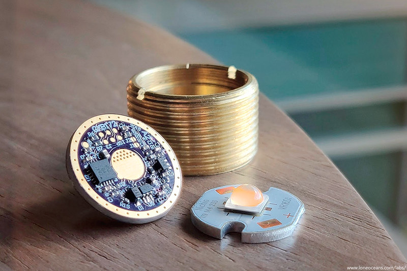
The S2+ flashlight comes with a threaded brass pill
where the driver sits in. The driver needs to be 17mm, and sits on a
small lip at the bottom of the pill, and is held in place around the
edge via a threaded retaining ring which screws on the circumference of
the driver. There is a fair amount of empty space above the driver, and
we can make use of that in designing our driver.
To make sure the driver would fit in the pill, I started
by doing some careful measurements of the internals of the brass pill,
so I could created 3D to-scale keep-out zones to make sure that any
component assembled on the driver would not interfere with the pill. For
example, having a component too close to the edge of the driver board
might result in it interfering with the brass side-walls, or retaining
ring.
In my previous explorations with different hosts, you
might recall that one main inefficiency in high current flashlights are
the contact points, specifically the tail-cap switch. Now ideally I
would like to go with an electronic-switch setup, but as of now I
haven't yet found a nice, elegant host for this purpose. The Convoy S9
appears to be the best one yet, but for now, we'll stick with the S2+ as
our benchmark mechanical reference.
Spring Selection
Choosing the battery spring for the driver is a small
but crucial step in the design. With battery currents expected to be
well over 10A, the choice of the spring both electrically and
mechanically is important. The spring does the job of not only
connecting the driver to the battery terminal, but also does the job of
securing the battery tightly in the body.
Typically for robustness and cost, steel springs are
typically used. They can be made from fairly thin wire whilst being
mechanically strong and robust, springy such that they do not deform
over time, but suffer from very poor electrical conductivity. In fact,
djozz on the BLF forums did an interesting test with various springs to
find out exactly how the material of the spring affects it mechanical
and physical properties. You can read the
details here. In
summary, steel springs have better strength and resiliency, but cannot
compare to beryllium copper, phosphor bronze or copper/brass springs.
Even gold-plated steel springs suffer from low conductivity. Djozz
concludes from the test that bypassing the spring using a wire or copper
braid is still the best, and I will definitely be doing it for this
build. But regardless, we'll take as much marginal gains as we can!
Finally, the last aspect is the size of the spring. We
want the spring to be fairly large in order to be mechanically strong,
but yet we want it to be as small as possible to take up the smallest
possible footprint on our driver PCB... a contradiction. Or is there? To
solve this problem, I simply flipped the spring upside down.
Most 18650/18350 with flat-top (unprotected)
construction have a 8-7.5mm flat area on the top, so this can be our
spring size constraint. All that's left is to find a spring with say
7-8mm diameter at the bottom and ~5mm at the top, and made of a good
high-conductivity material.
After a little searching, I found what I was looking for
on
Kaidomain. Specifically, the one on the left is a 5-6mm x 11mm x
0.7mm silver coated phosphor bronze spring, and the one on the right is
a 3.8-7.6mm x 10mm x 0.8mm bronze spring. The latter seems especially
attractive since it can be soldered upside down, taking up a very small
board space, while the bottom end is still large enough to fit well the
end of a lithium cell - though I'll be adding a small copper circle at
the end for even better contact. This constrains our spring pad on the
PCB to be about 5mm in diameter, and can also be used with the default
5mm spring I used in my GXB17 build.
Finally, this spring will also be bypassed with a
flexible wire for minimal ohmic resistance, ideally with silver wire! An
alternative is to replace the spring with a solid contact, such as a
copper cylinder or similar. This will have the least resistance, but
will require a good, strong tail-spring to maintain battery contact in
everyday use.
Programming
While working on my previous GXB17 and GXB20 drivers,
both which use Atmel ATTINY MCUs, programming them was always a little
bit of a pain due to the small footprint of the PCB, making connection
to the AVR ISP header difficult. Experiments with 50mil-pitch headers
and 6-pin Molex Slimstax headers proved to be less reliable than I was
hoping, so I developed a simple pogo-pin programmer instead which I've
called the PogoProg, or Pogo-pin Programmer.
For more information about the PogoProg, check out my
PogoProg page here on how you can make your
own. The pinouts are the same as in the
AVR ISP Mk 2 programmer and shown below.
As you can see the idea is pretty simple. On the PCB
there is a 2x3 50-mil pad connector corresponding to the 6-pins used for
AVR ISP Programming. A small PCB with six spring-loaded pogo-pins are
used to make contact with the pads. Although there are no alignment
pins, I found this to be a non-issue since the sharp pins grab the
copper pads fairly well. (I suppose the pads could be made with small
centering holes).
On the programmer there is a standard 100-mil 6-pin
header for connection to the AVR ISP 2 programmer or ICE programmer. To
avoid the need to power-up the driver for programming (since ISP does
not supply power), the PogoProg also has a micro-USB socket to accept 5V
power, and allows programming at 5V or 3.3V (with onboard regulator). I
now use this programmer to program all my micro-projects and it works
great! Please see my pogoProg page for
more information.
LED
Just as important as the driver, if not
more important (probably more!), is the choice of LED itself.
The LED is
the one that directly converts electricity to light, and it's pretty
amazing if you think about it, and all the work that went into LED
development over the past 30 years or so to get to where we are here
today. Indeed it was just a few years ago when Prof. Isamu Akasaki,
Hiroshi Amano and Shuji Nakamura were awarded the Nobel Prize for
Physics for the invention of the blue LED in the early 1990s, which
makes our white LEDs today possible.
It's also fun to see how
I've progressed in my little hobby projects back from one of my first
documented projects in 2003 where I made a LED
mouse-pad using some of the first blue LEDs I could get my hands on!
In this section, I'll describe the choice
of LEDs for two purposes - (1) achieving as much light as possible and
(2) creating the most beautiful light quality possible (while still
being very bright).
LED Choice for Brightness
Goal - find an LED which has the most lumens per watt
which can fit inside a small 18650 battery flashlight, and is capable of
achieving over 4000 lumens. Unfortunately this rules out the Cree XHP70
LEDs which the DN70 and TC20 lights use (Since the XHP70 at 7mm is
physically much larger than the already big XHP50 at 4.78mm, which it
itself much larger than typical 3.5mm XML LEDs often used), but the
choice is immediately clear - the Cree XHP50.2.
Above - graph showing Light Output and V_fwd against current through an
XHP50.2 J4 LED and XHP50 LED, created by Djozz from BLF.
In fact, Djozz again from BLF has done a whole slew of
tests on various LEDs and this chart above comparing a XHP50.2 J4 3A
5000K LED with a regular XHP50A is pretty clear.
This thread
describes it in more detail and all credit for the graph above goes to
Djozz.
Not only is the thermal resistance lower for the XHP50.2,
but the V_fwd is also significantly lower but some half a volt. So the
choice of our LED is clear - we want a J4 brightness bin (which is the
brightest bin of XHP50.2 LEDs) XHP50B LED.
Thermals and Heat-sinking
Image from https://intl-outdoor.com/
For heat-sinking, the LED needs to be mounted to a
suitable, good metal-core PCB. The best of these are metal-core PCBs (MCPCBs),
where the heat-pad of the LED is directly bonded to a solid PCB core. It
turns out that mountain electronics already sells a J4-bin XHP50.2 LED
mounted on one of the very best copper-core (even better than
aluminium!) 16mm MCPCBs made by Noctigon. So this will be our LED
and MCPCB
of choice. XHP50.2 J4-class on a Notigon MCPCB.
The Cree
datasheet rates the J4 class at 1239lm / 1120lm of luminous flux at
25/85C, at a nominal I_fwd of 1400mA. Unfortunately the datasheet only
goes up to 3000mA (where relative luminous flux goes up to 180% or
2230lm), but stops there, so we will need to use Djozz's chart. So what
do we need to do to achieve 4000 lumens? The chart puts us at a touch
over 6A, and a corresponding V_fwd of just about 6.6V, for a total drive
power of 39.6W. At 6.5A, V_fwd is still just over 6.6V (~43W), and light
output is close to 4150 lumens.
Based on this and with a driver and overall efficiency
(including wires etc) to be say 90%, our driver needs to be able
of handling ~47.7W in. We can design with the goal of having a ~6.5A
6.5V driver output or about 50W power handling, and a
stretch goal of 65W in, 8A 7V out - well over 4500 lumens!
Now let's see how does that compare to a XHP70 that
djozz also tested, to give an idea of how that will compare with
single-cell commercial 26650 flashlights of comparable brightness.
Graph of XHP70 performance, by Djozz from BLF forums
Again the above chart is from djozz in his
XHP70 test
(post 576). Here we can see that with the same 65W drive, the XHP70
achieves about 100-200 lumens more, so it is more efficient than the
XHP50, but not by a huge margin. However while the XHP50.2 maxes out at
5000 lumens, the XHP70 does some 500 lumens more, though its clear at
this point that thermals are the likely main limiting factor. If
possible, we may try to fit a XHP70 into our small flashlight, though
the target candidate is still the XHP50.2.
LED Choice for Colour Quality
For colour quality, we want an LED with a high Colour
Rendering Index (CRI). Unfortunately high CRI LEDs are typically far
less efficient than their low 70CRI cousins, but I think they more than
make up for it with their beautiful colour. As a result, after achieving
the goal of creating an extremely bright light, I'd also want a more
sensible flashlight with amazing colour, but still being fairly
bright. In my past experiences, I know that Nichia LEDs seem to
produce a much nicer tint than the Cree LEDs, even the 90CRI ones. So I
decided to try to see if I could get a Nichia LED to fit this project,
instead of using a high CRI XHP50 (like I did in my previous
GXB20 projects!).
Fortunately Nichia does make some XHP50 equivalents -
the 144 series! Like the XHP50, they are also a 4-die LED and are
essentially four 219C dies mounted together. Unfortunately, they are not
as easily available as Cree LEDs since Nichia does not sell to
distributors like Mouser or Digikey. In addition, the 144 series has a
completely different pad design than the Cree XHP50, so you cannot use
existing MCPCBs. Fortunately, Clemence from BLF has done some amazing
work with Nichia LEDs, and is now offering some of them for sale, and he
has also created some custom MCPCBs for them too!
The 144 LEDs measure about 4.65mm square, so they're a
little bit smaller than their 5mm XHP50 competitors, but this means that
they will fit our host light easily!
I ordered some Nichia
NV4W144AM sm563 E1000 R9050 LEDs from Clemence, along with his
self-designed VR16S1
heatsink from his shop here.
Many kudos to him for offering Nichia LEDs and his excellent
self-designed MCPCBs to the hobbyist community. This project would not
feature a Nichia emitter without his work!
So how bright are these LEDs?
Graph and test results by Djozz from BLF forums
Once again Djozz has done some great work testing out
both a 90CRI and 70CRI version of the 144 LEDs
here. Brightness of
the LEDs are very good, in fact closely tracking a XHP50A in brightness
up till about 6A (3500 lumens), before falling away.
Comparing the red
and orange, you can see again how thermals do play a big role in LED
light output. The driving voltage of the 144 is very low compared to the
XHP50A, but in line with the XHP50.2.
Graph and test results by Djozz from BLF forums
And finally, comparing a 90CRI and 70CRI LED, we can see
what a difference in terms of light output low CRI and high CRI has. So
back to an estimated nominal drive current of 6.5A/6.5V or so, we reach
the limits of the Nichia 144 LED, and should expect some 3500 lumens of
low CRI light (N/A for us!) or about 2500 lumens (for the 90CRI version). The sensible approach
here is to keep the turbo drive around 6A at ~6.3V, or even less for
everyday use. :)
*Other single-die LEDs for comparison
As a footnote, I had to justify the reason for this
whole project. Why is that so?
Turns out, there is in fact a way of
driving regular ~3V single-die LEDs via a single cell, using a very simple yet
effective method to achieve extreme brightness - the direct
drive method. This is also often referred to a a 'FET DD"
method since the driver is essentially... a very low resistance MOSFET
shorting the lithium cell directly across the LED, where the current is
ultimately only limited by contact resistances, wire and switch
resistances, and the resistance from the LED and battery!
Photos above from http://www.luminus.com
In real life, people often report some 6 to 9A of
current drive. So I tried to find the most powerful single-V_fwd LED in
a reasonable package, and I found the Luminus SST-40 and SST-90 LEDs.
The
SST-40-W comes in a reasonable 4.95 x 4.8mm size, but the SST-90 is
a little too large at 10x11mm, so I'll only be considering the SST-40.
Though it has to be said that the
SST-90 is in fact rated at 4000 lumens at a whopping 18A (V_fwd 3.87V at 9A).
The SST-90 is, at time of writing, the most powerful single-die emitter
(which can be purchased easily and at a reasonable cost to consumers).
Graph of SST-40 N4 performance, by Djozz from BLF forums
Turns out djozz also did another excellent investigation
of the SST40! So
what does this claimed 15W 5A 1650lm on-paper LED have to offer? Well it
turns out that the SST40 does track very closely to the Cree XML LEDs at
the same current, but it did so with much lower V_fwd! Djozz reported
that the LED died in the 'classic' way, where the bond wires on the LED
melted. Based on this, we can probably safely say that the maximum you
could push a single-voltage LED to is at 9.5A or so at around 4V. While
38W certainly is very impressive, it 'only' achieves a maximum of 2400
lumens and does so at significantly more power than my GXB20 driver.
So even with a DD FET with one of the very best
single-voltage LEDs, it's not possible to get to 4000 lumens reliably. Now the
story is a little different with a 3-emitter (in parallel) FET-driven
LED light, which is possible with a single 18650, and some 6000 lumens
should be achievable!... but I suppose we won't have half as much fun as
we are having now with this Boost driver design! ;).
Electrical Design
Electrical Architecture
Having had some experience with my GXB drivers, the
architecture of this boost system is actually fairly simple and
essentially as close as 'textbook-style' as you can get!
The heart of the driver is the MP3431/29 integrated
boost IC. Below is the typical application, configured in
constant voltage output, controlled via resistors R1 and R2. We need to
modify this for constant current output instead.
MP3431 typical application notes, from MPS's datasheet
For the control system, I had previously taken apart a
commercial H1-A 22mm boost driver and I decided that the control system
was better than what I had used previously in my GXB17/20 driver since
it used fewer components, so I have adapted it with changes. Essentially
the control takes a low-side voltage measurement from a sense resistor,
and compares it with an analog voltage generated via PWM from the
microcontroller.
In order to sense the current, the LED is driven from
Vout of the MP3431, in series with a low-side current sense resistor,
R_sense. The voltage drop across R_sense is fed into one input of a
low-input-offset Operational Amplifier. The other input is connected to
a filtered DAC output from our microcontroller. In this case, I'll be
using a ATtiny841 to generate this analog value via a high frequency
10-bit PWM, low-pass filtered to provide a DC compare voltage, scaled
accordingly. The output of the op-amp is then tied to the feedback pin
of the MP3431, which is itself also tied to a nominal resistor feedback
network (to produce the nominal 6V output). This completes the feedback
loop and the system now has true constant current regulation.
In order to perform the auxiliary functions, a 2.5V LDO
provides a stable and accurate 2.5V rail precise battery voltage
monitoring, generate a stable reference voltage for constant current
control, to power a digital temperature sensor, and to interface with
the EN-pin of the MP3431. The rest of the MP3431 is configured carefully
to suit our specific operating requirements (such as choice of
compensation network and operation modes - the datasheet describes how
this can be done).
Component Choices
Low Drop-Out Voltage
Regulator
The choice of this LDO is fairly straightforward and not
too critical. I
wanted a decent performance 2.5V regulator capable of ~100mA or so, and
importantly, come in a small package size, and made sure it didn't
need some sort of huge output capacitor for stability. I decided to use the SC-70
package due to it's availability, ease of soldering, despite its small
size.
A quick parametric search on Digikey for LDOs with SC70
package and 2.5V / >150mA and sorted for lowest cost reveals some choices including the
TLV70025DCKR
and
TPS71725DCKR,
good for 5.5 and 6.5V input. For our purposes of 1S operation, this is
OK, but we will need at least a 10V input regular for 2S operation, and
we may have to go up in size to SOT23 packages or other harder to solder
ones. For now, either SC70
device will work just fine. In order to make programming work via ISP
without back-powering the boost converter, a schottky diode is added in
series. In the future, the TPS709/706 may be used instead to reduce part
count since it has in-built reverse protection, but comes only in a
'large' SOT23-5 package, or harder-to-solder WSON-6.
Operational Amplifier
The constraints for the amplifier is simple. I needed a small
Op-Amp capable of rail-to-rail output, capable of operating at the
designed running voltage of 2.5V,
have a fairly low quiescent current (<50uA), and most
importantly, have
a low input offset voltage (on the order of uV) and low drift over
temperature. I did a quick parametric search on
Texas Instruments and selected a low-offset voltage (<100uV), a miniature SC-70 package, a minimum voltage of 2.5V, and I
was left with a few options including the OPA333, the cheaper version
TLV333, and a lower spec one (OPA317).
A quick search on digikey also confirmed my choice that
the 333 series was indeed a
decent choice. Since I'll only be building a few of these, the
OPA/TLV333 is a good choice so I settled on this op-amp. I could have
gone for smaller packages with excellent performance like the OPA2333P
but they're a little difficult to solder by hand and cost $3+ a piece!
I've managed to find some other op-amps as well including some from
Micrel and Maxim, but they seemed a little more finicky to heat during
hand-soldering than the OPA333 so I've stuck with that for now despite
the price. I'd imagine they'd all do just as well if manufactured in a
fabrication plant via proper reflow.
Temperature Sensing
In my previous GXB implementations, I used a NTC
(negative temperature coefficient) resistor in a voltage-divider
configuration in order to determine temperature readings. This worked
ok, but the temperature-resistance relationship of the NTC was
non-linear, and I wound up having to create my own look-up table, which
was messy, un-portable, and not particularly accurate. As a result, I
decided to use a dedicated temperature sensor IC this time just for fun
(obviously, more expensive though).
For this I decided to use the Texas Instruments
TMP103, which
is a low-power digital temperature sensor with I2C, and comes in an
extremely small 0.76 x 0.76mm 4-WCSP package - basically the same
footprint as our original 0402 NTC! It's capable of reading temperatures
to a resolution of 1C and supports I2C and SMbus, perfect for
interfacing with our MCU. It also operates well within our 2.5V supply
range (1.4 to 3.6V).
This particular device will be difficult to solder, but
considering it's only a 4BGA, it should be very doable with a hot-plate,
hot-air or reflow oven specially since the DSBGA already comes with
solder balls on the device and all it needs is a good amount of flux and
no additional solder paste on the pads to solder - it's easier than it
seems! You just need some magnification and a good pair of needle
tweezers.
Boost Inductor
The boost inductor is the key component in a boost
converter to generate a higher output voltage than the input voltage. In
this design, the inductor is also the largest component. An inductor
with a large inductance will result in less ripple current and lower
peak inductor current, so we want to maximize the inductance of our
inductor. However,
increasing the inductance usually results in a combination of the
following: increased inductor size,
lower saturation current, and higher series resistance. We want to find
an inductor which is as small as possible, yet have sufficient
inductance, high saturation current, and low series resistance (at a
reasonable cost!).
We know that the desired output current for the GXB172 is about 6.5V
6.5A nominal. A good estimate of a suitable inductor
ripple current is about 0.2 to 0.4 of the input current. First we
calculate the maximum input current:
Iin_max = (Vout x Iout_max) / (Vin_typ x eff)
Picking Vout = 7V, Iout_max = 8A, Vin_typ = 3V and eff =
.90, we arrive at Iin_max = 15.6A. Let's pick
0.2 of 15.6A and we get ΔI_L = 3.12A. Using this, we can estimate the right
inductor value:
L = [ Vin x ( Vout - Vin) ] / [ ΔI_L x fs x Vout ]
Using fs = 600kHz, Vin = 3V, ΔI_L = 3.12A, we arrive at
L = 1.00uH for Vout = 8, and L = 0.86uH for Vout = 6.5. According to the
MP3431 datasheet, a recommend value for the boost inductor is 1.5uH, so
this sounds very much in the ballpark (higher inductance will allow for
lower ripple at the cost of a more expensive indcutor for the current
rating). Let's find out the required current
rating for the inductor.
To do this, let us assume the worst case scenario of our
boost converter running at 80% efficiency. Hopefully in real life, this
number will be greater or close to 90%. Let's determine the duty cycle D
for the minimum input voltage (where input current is the highest) at
maximum drive.
D = 1 - ( (Vin x eff) / Vout )
From this we can calculate the peak inductor current,
which the integrated switches and / or diodes also have to withstand.
I_pk = ΔI_L /2 + I_max / (1-D)
Where I_max is the maximum output current of 6.5A nominal. From this, we find I_pk = 19.16A, so our inductor needs to be able to handle this peak current
without saturation. Note that this is also within the 21.5A maximum
switch current for the internal FETs of the MP3431.
In my GXB20 and GXB17 builds, I used the Vishay
IHLP2525CZ
inductors which were quite decent high-saturating current inductors
measuring 6.5mm square and 3mm thick. Looking at their 1.5uH inductor,
it has a 14mR DC Resistance, and a 18A saturation current (where L drops
by 20%), but the rating with a Δ40C is only 9A! So we need to look for
an alternative. I turned to the IHLP2525EZ series which are the same
footprint but 5mm tall, but the results were not looking too great
either.
I went one step up to the 3232CZ series, but even those proved
to be insufficient. Next I turned to another company - Coilcraft, whose
inductors I've used in my other power electronics projects, and I found
some that were perfect for this application!
Inductor Series
Inductance
Dimensions
DCR
Heat Current Rating Δ40C
Saturation Current (-20% for Vishay,
-30% for Coilcrat)
Even better than the XAL7030 but more than
twice the thickness. This is an ideal inductor except for the
height - it's basically a cube! ($3.14 ea)
Inductor images from Vishay datasheets and Coilcraft datasheets
After a quick investigation, it appears that the
XAL7030-222 and the XAL7070-222 are both
fantastic choices, with the latter being our first choice, and the
former being the choice for really height-constrained drivers. With the
fairly soft inductance roll-off, I expect both inductors to work fine.
Since the Coilcraft inductors have such high current handling
capability, I decided to go with 2.2uH instead of 1.5uH to further
reduce the ripple current. Note that the 1.5uH 7030 would probably be an
acceptable choice as well.
As a side note, Coilcraft also just released the
XAR7030 series, which
rises the inductor above the PCB so you can put small components under
it! It's a great idea, but its poorer thermals make it a less than ideal
choice for this particular driver. It does make sense for other more
sensible drivers though :) ...
Battery Choice
The choice of battery is an important consideration for
this project. At full power draw, the driver can be drawing over 15A
from the cell, so a high quality high-drain cell is required, which
maintains as high a battery voltage as possible during high current
discharge. Turns out a forum member HKJ on the CPF forums has been
testing out various batteries over the years and has an excellent 18650
battery comparison
site.
Comparison of LG HG2, Samsung 30Q and Sony VTC6 at 15A draw, by HKJ from
lygte-info.dk
One of the most popular high-drain cells is the common
and well-regarded LG HG2 (brown). After some comparison, I settled on
the Sony VTC6 (green) and Samsung 30Q (pink) cells as good candidates
for this project due to their excellent discharge characteristics,
capacity, and ease of availability. The chart above from HKJ's site
illustrates the excellent performance of all 3 cells at 15A current
draw, in particular from the Sony VTC6 which not only maintains a higher
cell voltage, but also has the highest capacity in this discharge test.
We'll use this for our flashlight build!
Layout
With the electrical design done, it was time to do the
layout. The layout is really what makes this driver 'work', since the
schematic is all pretty text-book and rudimentary, but a lot of care
needs to be taking for the routing, not just in terms of thermal
handling, but also in terms of minimizing loop area for high current
loops, keeping inductances low, and proper management of grounds.
Layout was done using 4 layers to simplify routing. These days,
4 layer boards are relatively affordable. This board was designed with
ease-of-fabrication in mind. As a result, I kept to OSHpark's
4 layer process
with a 5/5 mil trace space specification, 10mil drill, and 4 mil annular
ring. Using 4 layers instead of the 2 layers I constrained myself to in
my previous projects, helped routing significantly. Certainly going 0201 and using 4 layers would be even more optimal, as
would be using stricter PCB rules such as 4/4mil or 3/3mil! But then I
wouldn't be able to order them on OSHpark or low-cost fab houses.
Note that going to 2 layers bumps it up to 6/6 clearance, 10mil
drill and 5mil annular ring. For reference, my previous GXB17 was done with 10mil drill 20mil
via, 5/5mil clearance and width, 0.9mm/1.6mm vias for the output, though turned out just fine on OSHpark's 2oz 0.8mm process.
A little bit of work later and the routing is completed. It's a little
tight but I managed to keep all passives to be at least 0402 size or
bigger, with the smallest component probably being the 4BGA temperature
sensor IC. I might swap that one out for an alternative in the future,
but it works for now. While I didn't give much optimization to this
design, I did try to at least make a decent effort in making the layout
be as electrically sound as possible.
All 4 layers of the GXB172 (Rev A) board with internal planes
Rev A2 makes some improvements in silkscreen and placement, but
essentially everything remains the same
Care was taken to ensure best thermal performance as well as to reduce
any sort of loops especially on the power side.
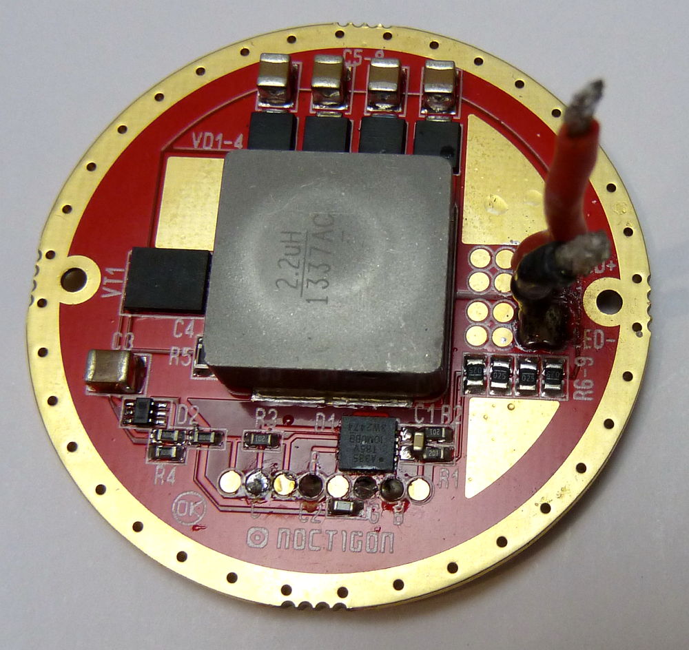
Above is a render of how the board will look like
populated. Notice how big the boost inductor looks like compared to the
driver! I was also constrained to using 1206 input and output
capacitors, though in real life you could stack capacitors for better
performance. Ideally you'd want to be using 10V capacitors and 16V
capacitors for the input and output sides respectively at 6V operation,
or 25V in the case of 12V operation.
Programming is done via a 50mil 6-pin pad array where a 6-pin header can
be used via contact-programming with my PogoProg. I decided not to go for the molex
micro-stack header since I had a poor experience using it in previous
projects
where it would often get stuck in the receptacle and pull itself off the
pads...
Input power comes directly across the perimeter of the
driver, and the centre spring. Output terminals are the two oblong pads
on the inductor-side of the PCB.
Software Development
Development Board
The GXB172 is a fully-featured programmable LED Driver,
so we need to write a little bit of firmware to handle all its features.
The target MCU chosen for this project is the
ATtiny841.
I chose this particular controller primairly because it came in a diminutive 3x3mm
QFN package, as well as having a decent 8kB of flash, 512b of EEPROM,
operating range down to 1.7V, two 16b timers, internal oscillator, and
fits well within the Arduino environment which I hope would be easy and
friendly to anyone hoping to build their own GXB172 or write their own
firmware for it.
It's no fun to work on a tiny 17mm PCB, so for
development purposes and to test functions out, I created a development
board, allowing me to test different functions, conduct measurements,
debug, etc all on a convenient platform!
I knew that I wanted to incorporate some fun new
features which I thought of only after developing my GXB17 and GXB20
drivers, and I figured that a simple 'dev board' would allow me to (1)
much more easily probe the board and (2) allow much easier firmware
development. I also added hooks for soldering on a second MCU (the Atmel
Attiny1616 is an interesting candidate since it's one of the new ones
after the Microchip acquisition), but for now I've gone with the
Attiny841 which is more capable than the Attiny85 or 84A I used
previously.
After about a day of work, I completed the GXB Rev 2
Development Platform board.
As you can see above, the dev board allows me to connect a whole bunch of
probes to it, my AVR ISP programmer, as well as input and out via screw
terminals, debugging LEDs, an E-Switch for E-Switch development, and two
footprints for different MCU options if desired.
Testing and firmware development was done with a very
powerful bench power supply, and a XHP50A-00-0000-0D0UG20E2 LED
configured for 6V operation, mounted on a large heat-sink as shown
above. The Dev board allowed me to finalize the electrical architecture
of the system and to easily develop firmware for it.
Firmware Development
After a little bit of work, my preliminary firmware was
completed! It's a fairly simple no-frills driver with one particular
mode structure shown below. Due to the fact that there are jumper pads
on the board, the GXB172 can be easily customized to have different mode
structures without reflashing - just bridge or un-bridge the solder
jumpers. Below shows a mode-scheme I find useful and fun:
'
The above flowchart shows the general operating states
along with error and fault conditions. The number of modes, memory,
special effects, battery cut-off, thermal regulation etc can all be
adjusted to whatever the user wants. Note that the temperature
thresholds are subject to change (see chart below).
Writing the firmware was actually a little more involved than it seems
because there are several tricks that are taken into account to ensure
that the system runs properly, and handles things like initial voltage
sag during turn-on in a robust and intelligent manner, among others.
Firmware version 1.0 has the follow default values as well as different mode
groups depending if X1 and X2 jumpers are set or not. Open jumpers
(default) are 1, shorted/bridged jumpers are set as 0.
More work to follow on the firmware when I get more time. I already
have many ideas how to improve it.
Chart showing different brightness vs. time values while playing around
with the best thermal control firmware for the flashlight...
One key aspect I worked on for a fair bit was the PID
thermal control, which aims to keep the flashlight at a fixed set
temperature when on boost modes. To do this, I had to optimize the
system with the flashlight case in mind, and conducted several
measurements with different PID coefficient values (some examples shown
above) to arrive at something practical and useful. The nice thing about
this system is that the driver will never cause the light to get too
hot, and external cooling of the light (e.g. immersing in water) will
allow the system to automatically ramp up the brightness (up to the set
mode).
The first stable firmware v1.0 was completed in Mar
2018. The design of the GXB202 is identical so the same firmware can be
used.
With the design optimized after tinkering around with the dev platform
and the firmware completed I completed the final layout of the
form-factor PCB and sent it off for fabrication.
PCB Assembly and Flashlight Builds
Assembling the PCB (Rev A)
With the PCB layout done, I sent the boards for
fabrication. I designed these boards with OSHpark's 4-layer
specifications and constraints in mind. The boards are very small so
they came back nicely. A quick check yielded no broken or shorted
connections that I could find, and I quickly went ahead to solder this
up. Because the components are fairly small, the difficult-to-solder
parts (inductor and boost IC) were reflowed
using careful application of solder paste with a needle and a reflow
oven (the 4BGA temp-IC doesn't need additional paste, just a bunch of
flux). The rest were soldered on manually by hand using needle tweezers,
a fine-tip iron and thin solder wire.
I put some boards together and I'm happy to
report that the only mistake I found was a single silkscreen error (C10
placement), but
electrically it all turned out good! Here's how it looks like, top and
bottom.
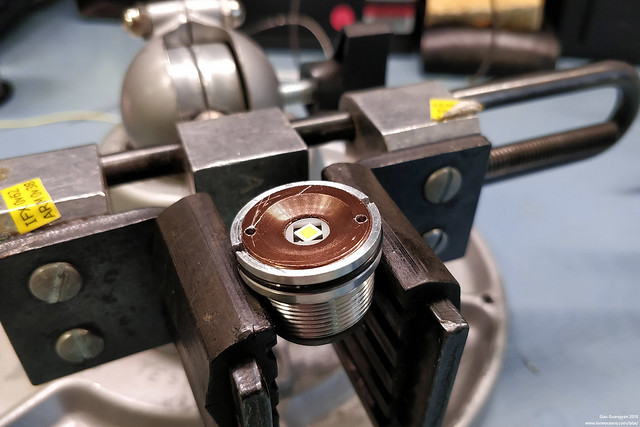
Above is it pictured sitting in a Convoy S2+ brass pill
which is my candidate flashlight for this driver. Note the big pads for
+ and - to the LED, as well as programming header pads (ISP), E switch pad
(SW),
two additional jumpers (J1 and J2), and one more auxiliary pad (A3) which can be use to
power an extra LED, or something else (e.g. I used this for a debugging
LED during firmware development!).
Above shows a side view of the driver. The big inductor
can be easily swapped out for a smaller shorter (3mm tall) one if your
host doesn't have space for a ~7mm tall inductor. Using a bigger
inductor allows better performance though with a higher inductance
(desirable) and lower DC resistor (desirable).
Fortunately the board came together without too much
difficulty and I never had any problems with the assembled boards- but I suspect for most hobbyists, this
may be a challenging board to assemble!
With the first few GXB172 drivers soldered up, it was
time to put it to the test in a flashlight! - Note, I tested them
on the bench first with a dummy LED just to make sure they were working,
before putting them in the host. Fortunately, no problems were found in
the layout and everything worked first time around!
GXB172 - Rev A2
A few small changes were made to the GXB172 at the start
of 2019 - a silkscreen error was fixed, a bleeder resistor (for some
tailcap light switches) was added, and components were move slightly to
allow a little more clearance for the retaining ring.
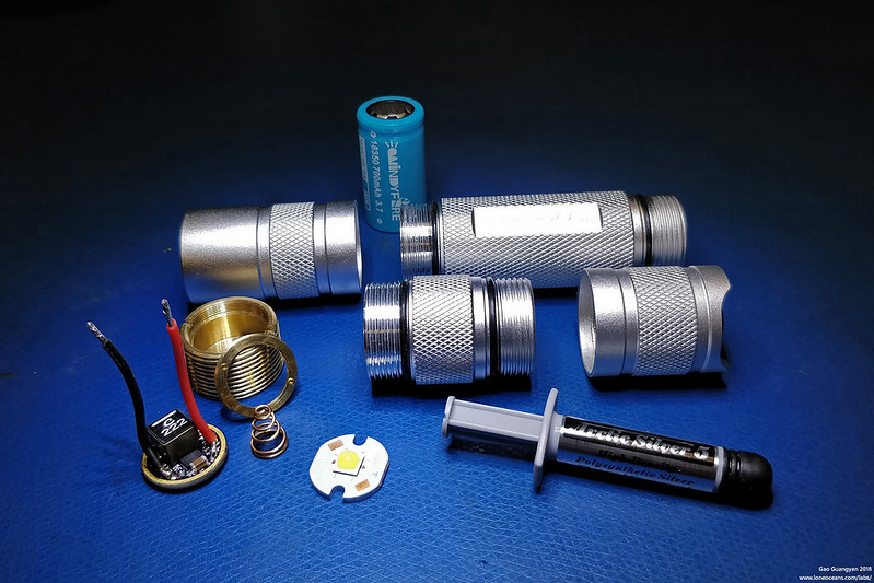
Above shows the completed GXB172 Rev A2 ready to be
assembled into the brass pill of the Convoy S2+ host (after soldering on
spring and wires), along with a 4500K 90CRI Nichia 144AM 6V LED on a
Clemence-designed 16mm aluminium core PCB. The electrical design remains
identical.
15 Mar 2017
First Build: 18350 Convoy S2+ Shorty, Clear, CRI90+ Nichia 144 with
GXB172
With the GXB172 driver verified to be working as intended, it was
time to put it inside a flashlight. For my first build, I opted
to make a high-CRI flashlight with one of the very best
multi-die LEDs available (as discussed above in this page). This
will not be an ultimate lumen monster, but instead, a
still-pretty-bright ultra-compact flashlight.
The LED of choice is the Nichia NV4W144AM sm563 E1000 R9050 LED,
mated with a 16mm VR16S1 aluminium MCPCB designed by Clemence.
This LED was reflowed onto the heatsink using solderpaste and a
reflow oven. When assembled with a GXB172 at 6A at around 6.5V,
we should be able to get about 2500 lumens of beautiful 5700K
90+CRI light.
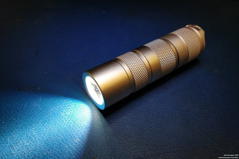
The flashlight host of choice was the venerable
Convoy S2+ which
is often available for just about $10 or so. Convoy is one of
the most popular brands of fairly high quality flashlights. They
are based in China, and over the years, have produced not only
excellent flashlights, but have also taken their customer
feedback very seriously yet keeping quality very high. The S2
line is one of their most popular, and designed around a single
18650-cell, a 17mm driver, and a 16mm LED PCB.
I was recently able to purchase one such host, but this time in
a very nice clear/anodized finish, showcasing the beauty of the
aluminium. I also bought a short-battery tube replacement.
Powering the flashlight is a WindyFire 18350 700mAh 3.7V cell,
one of the best hi-drain small cells I had on hand.
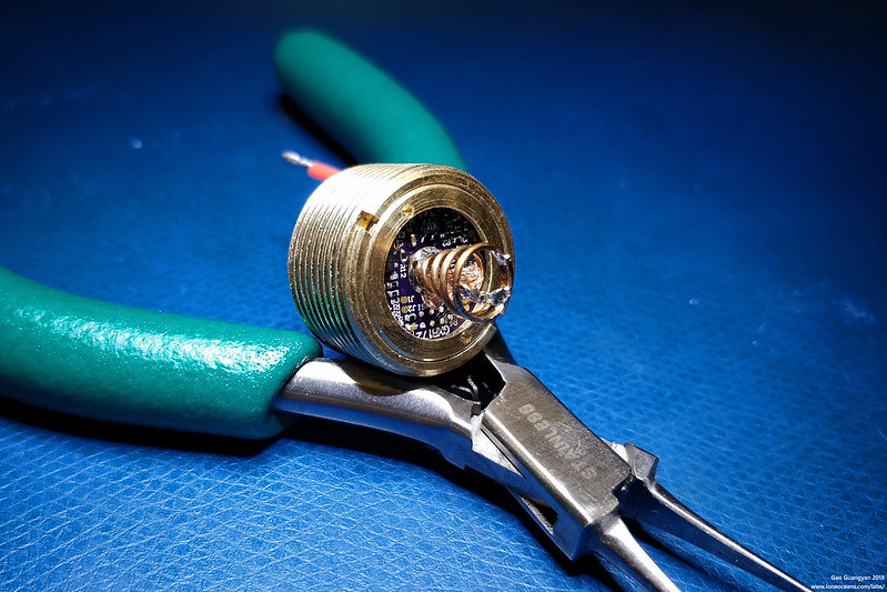
First I had to solder on a spring. It looks a little funny but
it works just fine inverted. As discussed previously, this was a
3.8-7.6mm x 10mm x 0.8mm bronze spring from Kaidomain.
Solder-wick was used for spring bypassing to reduce ohmic
losses.
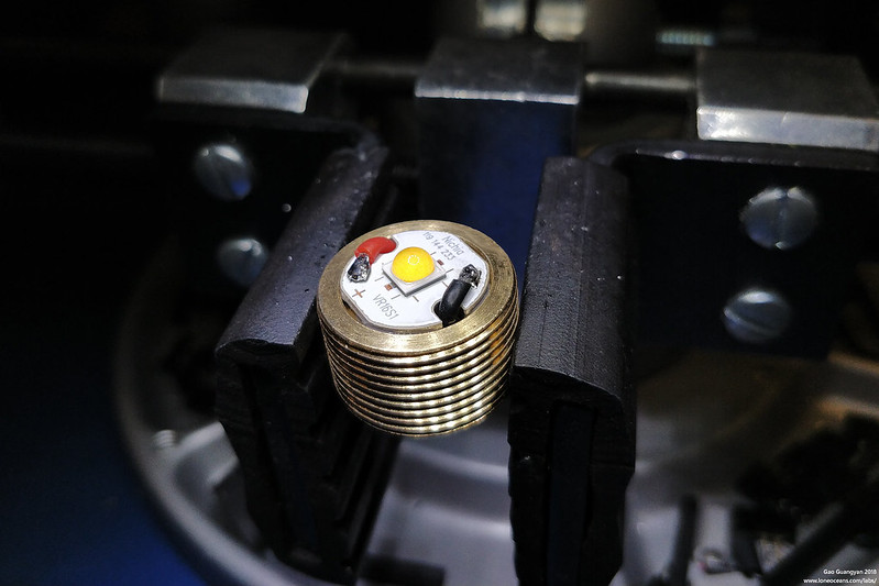
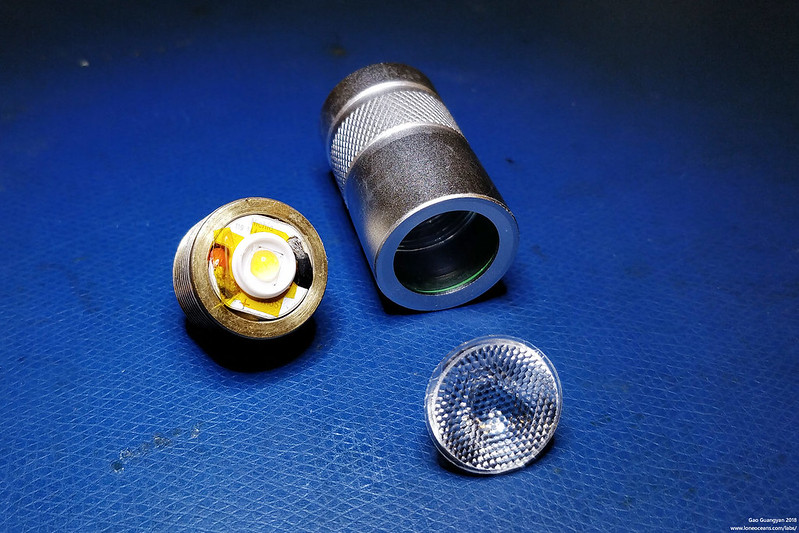
With the driver in the pill, next is the Nichia LED. Now this is
not the most efficient of LEDs in terms of being a
lumen-monster! Djozz has tested this E1000 LED and it 'only'
puts out ~2500 lumens at a 6A ~6.4V drive. But I really wanted
to make a high-CRI flashlight while still being very bright.
Don't worry, I have a J4 XHP50.2 LED up next for a >4000 lumen
light which will be coming next. The MCPCB was placed into the
brass pill with Arctic Silver 5 thermal paste.
Then it was time to put everything together..
... and it works exactly as expect with all the modes and
functionality working!
Because I've configured this light to be a 'shorty' build,
having it run at my originally intended 6A output would lead to a ridiculous ~3 to 4+
minutes of runtime on the 18350 battery (thermal throttling will kick in before that
though), so I later changed the modes for a more reasonable 4.2A LED
output (measured and verified). The result is about 2250 lumens
of beautiful CRI 90 Nichia light!
[Update Aug 2018 - I've since put this
flashlight through its paces bringing it on many camping trips
and it has performed admirably! I'm now confident enough to
bring this along as my own flashlight for outdoor adventures,
though I've swapped out the battery tube to accept the higher
capacity 18650 when necessary!]
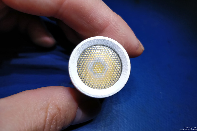
Diffuser Upgrade
Once problem though which I quickly encountered with the Nichia
144 LED and the regular mirror reflector on the flashlight, was
that the beam profile was fairly ugly to say the least! Due to
the phosphor deposition on the 144 LED die, the resulting beam
pattern was very much like a 'fried egg', being very yellow in
the middle, and turning cooler towards the edges. In order to
solve this problem I decided to swap out the mirror reflector
with a Total
Internal Reflection honey-comb diffuser instead.
I purchased a bunch of different beam profile diffusers
(different divergence) from Convoy's Aliexpress shop, and after
some tested, settled on the 45 deg one. This produces a wider
beam profile than the stock reflector, but it diffuses out the
yellow hot-spot beautifully and the result is better than I
could have hoped for!
The TIR optic works really well and produces a much softer,
wider beam (45 deg one used here), at the cost of slightly
reduced OTF (out of the flashlight) lumens and reduced thermal
performance (since the original mirror reflector was aluminium).
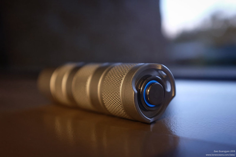
Tailswitch-Upgrade
Finally, I added some additional features to the light! I won't
cover them in detail on this page, but you can bet that it
wasn't just for looks! In fact, I consider them
essential to operating the flashlight with the GXB172.
The key reason is to reduce voltage drop at high current drain.
Just some quick information - when doing bench testing of the
GXB172 driver, I found that it was capable of drawing over 15A
from a single cell. This is a pretty large current, and we start
to see some major problems, specifically with switch resistance
and longevity.
In my previous lower-power GXB17/20 drivers (20W driver), these
drivers often pull something like 6 to 7+A from my batteries.
Recall that the first few hosts I used were cheap SK98-type
flashlights, and I quickly found that the tail-switches were
completely not up to the task of handling those load (they
melt). Since then I've had two out of three of those switches
fail, one where the contacts seemed to have welded together, and
another got so hot it melted the casing partially and failed
mechanically.
Granted these switches are not as robust as the Omten1288 or
similar branded switches used in the Convoys, but I was (1)
uncomfortable with having the switches frequently switch and
interrupt ~10 to 15A in my GXB172 driver, and (2) was
encountering problems with the significant voltage drop across
the switch resistance.
I was able to measure the switch resistance for several random
Omten switches, and they ranged significantly from ~40mR to
10mR, and varied depending on how got they got, and how used
they were. Omten switches are technically only rated for 1-3ADC
with a maximum contact resistance of <200mR
(http://www.omten.net/pbs1288-push-button-switch/pbs1288b-push-button-switch.htm).
The fact that people frequently use them in DD FET drivers at ~6
to 10A is quite amazing!
However let's take a ~30mR average for a new Omten clicky
switch. Even at 30mR resistance, at 15A, the voltage drop across
just the switch is 450mV!
Even for a high quality cell, at 15A discharge, this can result
in the driver input voltage falling and approaching 3V. The
result is far from ideal since the driver sees that the input
voltage is low, but to compensate for a fixed output, it has to
draw more current, causing the voltage drop across the
flashlight contacts to increase, etc etc. The result is a
detrimental feedback loop, eventually resulting in the driver
sensing that the voltage is too low, and triggers battery
protection, even when the battery is not anywhere near depleted.
As a result, I created a prototype switch, replacing the clicky-switch
with a very low resistance MOSFET.
The result is theGFS16
tailswitch system (I will be writing a proper page on this), but it
is an integral part of the GXB172 system. By replacing the
mechanical switch with this system, the voltage drop across the tailswich drops by several 100s of mV, improving performance of
the GXB172 significantly and greatly improves runtime. The GFS16
features an on-board tiny rechargeable battery which drives the
gate of a very low R_ds_on MOSFET when ON. In addition, it
features a very low-resistance Notigcon Beryllium Copper
tail-spring removing the need for a spring bypass.
And finally, it has some taillights... which add additional
functionality to indicate if the battery voltage is low or not,
and changes colour accordingly :).
With that, the first GXB172 flashlight is officially complete!
May 2018
Build 2 - 18650 SK98 XHP35HI with GXB202 at 12V+ output
Update (May 2018) - The GXB172 now has a
larger cousin, and runs great at 12+V output (with the same
single-cell input!)
Back in 2017 when I first embarked on my GXB driver projects,
the main target flashlight case was the SK98 with a zoomy lens.
The flashlight requires as 20mm driver, so the GXB172 would not
fit. However, I always thought that the flashlight would be a
nice host for a XHP35HI LED since it would make a low-cost but
decent 'throwy' flashlight. The SK98 requires a 20mm driver and
a 20mm MCPCB. Importantly, the XHP35HI comes in only a 12V
configuration.
I thought it would be the perfect time for me to modify the
GXB172 to a larger PCB, and test it out properly at 12V-out
configuration. After a little bit of time, I managed to complete
the GXB202! - the 20mm version of the GBX172!
The larger board size allows for much better clearance around
the board as well as more space for larger passives. I was able
to use 1210 capacitors for both input and output rails, and I
was also able to relax placement of other components and pads.
Otherwise, the layout and schematic remains identical and both
driver sizes share the exact same firmware and functionality.
This particular build was optimized and compensated for a
nominal 2.5A 12+V output.
As a gift for those who are reading closely, here's the
board
files for the GXB202 Rev A... ;) The motivated can try to
assemble one themselves with a little bit of modification to the
GXB172 BOM..
For the LED, I chose the highest bin XHP35 HI I could buy (sadly
only a D4, 5000K, not the top-bin), from Kaidomain, together with their in-house
MCPCB. This was installed into the pill with Arctic Silver
thermal paste. The GXB202 driver was installed and it fit
perfectly. In this case, the GXB202 was configured for 12-14V+
output with a maximum of 2.5A drive. A BLF forum member TA
measured 2570 lumens from a E2-bin LED at 2.5A, so this LED
should be putting out a good ~2396 lumens at 2.5A drive current.
A bench test was also conducted at a variety of power levels
(just before I trimmed the wires and put it all in the
flashlight), ranging from the lowest setting (about 2-3mA @10.2V) to the LED,
all the way up to 2.50A at 14.70V (36.75W to the LED). Battery
input was measured at just over 40W, giving us about 90% total
efficiency (including wires etc, probably a little better in a
well-put-together flashlight), with higher efficiency (>95%) at
more realistic power levels.
I'll probably do a quick write-up about the GXB202 in more
detail in the future.
---
[More to come soon including a Copper S2+ build with a XHP50.2
J4 at 4000 lumens!]
Results
Jan 2018
Preliminary Measurements
Here are some results while testing the GXB172.
Above shows a scope shot of an early GXB172 prototype in
operation with a XHP50A LED in 6V configuration (on a heatsink), powered
by a LG HG2 18650 battery. For this test, I wrote a very simple test
program which ramps up the LED current from 0 to 6.5A linearly to see
how it performs. Note that in this version, the inductor used was a
Coilcraft XAL7030, which is a little less efficient than the XAL7070
which subsequent builds use.
Above you can see the input voltage in yellow from a LG HG2 lithium
battery (excuse the voltage drop, my battery cables were fairly long!..
and I had to use a battery since I had maxed out the 8A of my power
supply!), the output voltage (magenta), the output current (green) and
the switch node (cyan). The driver was hooked up to a XHP50A LED on a
copper MCPCB and clamped onto a heat-sink (same as the one in the photo
above).
Looking at the peak of the current drive, the GXB172 has an output of
some 7.24V at 6.5A (47.06W)! This was at an input voltage of 3.4V and
about 15.6A on the input (clamp meter measured) for a total efficiency of around
89% (efficiency is much higher at more 'reasonable' drive levels!). This is about as
high as one can go without increasing inductor size (e.g. going up from
the Coilcraft XAL7030 to say the XAL7070) and dropping the ripple current, since we want to have some
headroom above the inductor and switch peak current! So far it seems
like the driver is not thermally limited per-se, i.e. the LED produces
so much more heat that it'll end up heating the driver up more than the
losses in the driver.
Mar 2018
Convoy S2+ Build with GXB172 and Nichia 144 LED
I put together a really quick video to show the GXB172
in action (preliminary firmware). Unfortunately, this video
production is fairly poor quality so please excuse this; I'll make a
better video in the future.
In the video I go over the basic firmware functionality
of the GXB172. The light is extremely bright, but my camera stops down
pretty quickly. Also the candle-mode is a little silly right now since
I'm using a 5700K LED (too blue). However I have plans for some nice, warm emitters
which will be great for camping! (Note: this video was taken before the
S2+ was outfitted with the improved TIR diffusing optic).
[More to come soon and thank you for visiting my page]
Useful Links
Forum Related
Springs
- Djozz's test on the conductivity of different springs on BLF
TLF M43 - Review & Teardown of the Noctigon Meteor M34 on the German
TFL forums & Photo on
Russian Forum &
BLF &
Chinese Detailed Review
TFL XHP70 - Detailed review of the XHP70.2 Cree LED Buck and Boost
Drivers - Including
H2C and H1A Teardown on BLF BistroHD -
Community OTSM Driver Firmware on BLF
General Links
Imalent DN70 - Flashlight Review of a 3800lm 26650 light by ZeroAir
Thrunite TC20 - Flashlight Review of a 3800lm 26650 light by ZeroAir BudgetLightForums - Thread of this project
on BLF as it progressed
Cree XHP50.2 - The next generation Cree XHP50B LEDs Convoy
Flashlights - Official Convoy shop on Aliexpress TPS61088 - 10A
fully integrated synchronous boost converter TPS61178 - 20V
fully integrated synchronous boost converter with load
disconnect
TVL700 - 200mA
standard SC70 LDO 6Vin max REG102 -
250mA low-noise SOT23 LDO 12Vin max no cap needed TMP103 - Two
Wire Digital Temperature Sensor
MP3428A - 19A 20V Synchronous Boost with Input Disconnect
MP3429L00A - Dev board for MP3429
MP3431 - 21A 20V Fully Integrated Sync. Boost Converter
More to come soon
Back to main page
(c) Gao Guangyan 2025
Contact: loneoceans [at] gmail [dot] com
Loneoceans Laboratories. Copyright (c) 2003 - 2025 Gao Guangyan, All
Rights Reserved. Design 3.
Removal of any material from this site without permission is strictly
prohibited and will result in infringement of copyright laws.br>
Disclaimer: Projects and experiments listed here are dangerous and should
not be attempted.
www.loneoceans.com/labs/
... page generated in 0.00014 seconds


 What is the GXB172?


 '
'


