17mm Single-Cell 20W LED Driver
|
GXB17 - Programmable Constant Current Boost Driver
Introduction
 The
GXB17 is an evolution of my previous project, the
GXB20 flashlight LED driver, which was my
original high power single-cell programmable LED boost driver. The
GXB17 is an evolution of my previous project, the
GXB20 flashlight LED driver, which was my
original high power single-cell programmable LED boost driver.
After the success of the GXB20 project, I had a lot of requests from the
flashlight hobby community for an even smaller, 17mm version. It turns
out that many high performance flashlights (which are driven by common 18650 lithium cells) all use
17mm drivers. In addition, I found that there were in fact
many beautiful flashlight host bodies which allow you to assemble your
own light, with your choice of LED + heatsink, and a suitable driver
(much better than the SK98 host I used in the GXB20 project).
These new flashlights would be a perfect host for a new, 17mm driver.
Hence the GXB17 was born. The goal was simple - create the same powerful
flashlight like in my GXB20 project, but in an even more compact flashlight body,
and using either one of
Cree's latest 6/12V XHP50.2 LEDs, or one of Nichia's 6/12V 144M LEDs.
The GXB17 was created by keeping the electrical design essentially
identical to the GXB20 V2, but shrinking the PCB space down, improving
routing, and having a more careful choice of (smaller) components. For a driver
with just 0.35" inch-square in
area, it handles 20W of power. The result is an improved version of the
driver with just 72.3% of the original footprint.
I will not go into the details of this project too much because much of
it is the same as the GXB20 driver, and its background and
engineering choices have already been covered in depth. Please feel free
to see that page for more information :).
Project Results

I'm happy to say that after some on-and-off work between busy schedules, the GXB17
project culminated in a 18350 Convoy S2+ flashlight build, powering
a Cree XHP50B LED at ~6V/3A, via a single 18350
(shorter version of a 18650) lithium cell. The result is ~2000
lumens of bright white LED light in a significantly smaller body than my
previous GXB20 flashlights!
GXB17(v1) Feature-List
What is the GXB17?
The GXB17 is a smaller form factor of the
GXB20 driver I
made for fun prior to this project. The GXB17 is a simple
constant-current single-cell, programmable, boost, LED
driver. It is designed specifically to drive 6V 3A LEDs like the XHP50
and Nichia 144 LEDs from a single ~4.2V lithium cell, and can also be configured to run in 9V and 12V
output, with a nominal maximum power of around 18+W, and higher in boost
for shorter durations and ultimately thermally limited. That said, the
driver is limited to 13.2V output from the main boost IC, so it may have
limited use in some ~12V drive configurations using high V_fwd LEDs.
The GXB17 incorporates all the features of the GXB20, but as its name
implies, is only 17mm in diameter. The GXB17 is a true constant current
driver which takes drive current feedback and regulates the output
voltage to match the desired current. The driver is fully programmable
with an on-board ATtiny84A and includes features such as temp-sensing,
battery voltage sensing, off-time memory, and runs at >90% efficiency at
most output levels. It also has pins for an optional e-switch if
desired.
Finally, the GXB17 was designed as a fun hobby project, and definitely
not designed to be a commercial driver in mind - i.e. no optimization
was made for cost, component count or ease of fabrication! That said,
it's a fairly full featured driver and I hope it will be something all
hobbyists can enjoy!
Feature List
- Single-cell 1S (e.g. 18650) 2.7 to 4.3VDC input (6V
max)
- Boost Driver: True Constant Current drive
- Nominal 18W out (6VDC at 3000mA), (9VDC at 2000mA) or (12VDC at
1500mA)
- Designed primarily for XHP50 CREE or Nichia 144-series LEDs running in 6V configuration
- 17mm Driver Board Size
- Low-Battery-Voltage cut-off
- Programmable with ATtiny84A MCU
> Configurable modes with EEPROM memory
> Real-time temperature sensing and cut-off
> Two extra GPIOs for Mode Select
> E-Switch capable with firmware
- Over 90% efficiency throughout most output ranges
- 256 levels of true constant current brightness levels
- Off-time Capacitor and mode-memory
- 5/5mil routing on single 2-layer PCB for reduce cost in
fabrication
 In this page, I'll outline the motivations of this project, how I
designed this driver, and how I put them all together. Hopefully this
will also be a useful resource for many like-minded hobbyists around the
world who are also fascinated by flashlights and power electronics :-).
The GXB17 design including schematics, layout, firmware, and
architecture are available on this page under the
Creative
Commons License. In this page, I'll outline the motivations of this project, how I
designed this driver, and how I put them all together. Hopefully this
will also be a useful resource for many like-minded hobbyists around the
world who are also fascinated by flashlights and power electronics :-).
The GXB17 design including schematics, layout, firmware, and
architecture are available on this page under the
Creative
Commons License.
Project Status
(Feb 2018) - The project is officially completed and
fully functioning, and deemed to be successful in achieving its
goals, reaching ~2000 lumens while powered from a single 18350 small
battery... however, now that I've achieved the goal of making a sensible
single-cell flashlight, the question remains - how bright can I
really make a single-cell single-LED flashlight?

Here's a preview of a DC current reading to a 6V
configured Cree XHP50, and we still have a lot of room to turn things
up...
Stay tuned for the next project!
Jun 2017
Electrical Design
The heart of this project is to create a suitable boost
driver, and we need to do some electrical engineering to get us there.
Designing the GXB17 was a little bit more work than my previous GXB20
driver, mostly because of its much smaller size. It only has 72% of the
PCB space as the GXB20, or 60% the footprint of competing 22mm drivers!
In addition, I wanted to design it to fit common and affordable PCB
fabrication requirements, and not go to a 4 layer board.
Furthermore, I wanted to incorporate all the features of
the GXB20 with no compromises in power output or features. I know the
design can be significantly optimized for less parts etc, but I liked
the configurability aspect of the GXB20, so I simply ported over the
entire schematic and did a new layout for the GXB17 with only a few
component optimizations.
Electrical Overview
The main electrical design for the GXB17 remains
essentially the same as the GXB20. In order to keep the size even
smaller, some more expensive but smaller passives (e.g. the input and
output capacitors) were used instead.
The heart of the GXB17 is the Texas Instruments TPS61088
10A full integrated synchronous boost converter. This boost converter
was configured in forced PWM mode to reduce audible switching noise
during low power operation. Instead of using regular voltage feedback,
the GXB17 implements constant current control. The output current is
sensed via a 30mR current high side current shunt, and the current
measured and amplified 12x via a TI INA139 high-side current shunt monitor. This
voltage is then amplified again via a regular TSV991 op-amp in
non-inverting mode, and the gain dynamically adjusted on the fly via a
MAX5394 256-tap 50kR digital potentiometer. This output is then fed back
to the TPS61088 which compares it against a 1.204V internal reference
for output regulation.
Brightness control is determined by setting the wiper position
on the digi-pot. This is done over SPI via the main microcontroller,
which is an Atmel ATtiny84A. This IC was chosen primarily because it
comes in a very small but still home-solderable 3x3 QFN package, and is one of the easiest MCUs to
program using the standard hobbyist-familiar Arduino environment.
Off-time sensing is done using an off-time capacitor. Power to all
peripherals and the MCU, except for the current monitor, is supplied via
a 2.5V TLV700 LDO. To handle the low voltage, the digi-pot was chosen
for its integrated charge pump. Temperature sensing is done via an NTC
soldered to the ground plane (with temperature look-up table
pre-computed and programmed). Likewise, the ATtiny84A also handles
battery voltage sensing. Programming is done via regular AVR ISP but via
50mil 2x3 pads on the PCB, like the GXB20 V1. Programming then requires a simple home-made
100mil to 50mil adapter to be made, which can then be soldered or
press-fit to program via the Atmel ICE or AVR ISP II programmer.
The firmware was written in the Arduino environment due
to is extreme ease of use and hobbyist popularity so others can make
easy improvements or modifications. The code was compiled using the
Arduino IDE and the hex file flashed via AVR ISP II.
Because the GXB17 was primarily designed for 6V 3A output to drive XHP50x or Nichia 144 LEDs, some component values were chosen
to optimize for this output configuration. However, the driver can be configured
for 9V output or 12V output, though the maximum drive voltage of the
TPS61088 is a little limiting at 13.2 - some 12V LEDs require higher
voltages at high drive currents which may exceed 13.2V.
A future version of the GXB17 may include the use of the
TPS61178 which is a new, smaller, higher voltage (20V) boost converter
also by TI, but was just only starting to be available during the
development of the version 1 of the GXB17. This may allow a more
efficient layout as well as more configurability options for future
revisions.
Schematic
The schematic remains very similar to the
GXB20 V2 which is what the GXB17 is based upon.

The GXB17 design including schematics, layout, firmware,
and architecture are available from this website under the
Creative Commons License.
As annotated above, component values can be modified to
suit the desired output drive voltages. Hopefully this will be useful
for anyone interested in making their own GXB17 V1 driver too!
Layout
With the electrical design done, it was time to do the
layout. To increase space further, I opted for the use of a smaller
spring, specifically one just 5mm in diameter.

Above is the completed layout of the driver; a little
hard to see but the board space is fairly well used up, though I think I
could probably optimize it even more with a little more work.
Programming is done via a 50mil 6-pin pad array where a 6-pin header can
be used via contact-programming. I decided not to go for the molex
micro-stack header since I had a poor experience using it in the GXB20
V2 where it would often get stuck in the receptacle and pull itself off the
pads.

Above is a render of how the board looks like. Care was
taken to optimize power and logic traces so they interfere as little as
possible, yet still fit completely on a 17mm 2-layer PCB - and I tried
to use no smaller than 0402 components for almost the entire design.
Certainly going 0201 and using 4 layers would be even more optimal, as
would using stricter PCB rules such as 4/4mil or 3/3mil! But this will
increase PCB fabrication costs significantly!

Above shows a quick preliminary to-scale comparison
between the GXB20v2 and the GXB17v1 driver. Note
that while it looks like the outside ground ring of the GXB17 is not
'closed', it is in fact closed. It looks like there is a a little gap
due to the soldermask printing - I had to add the soldermask since I
could not avoid a small trace running right along the periphery of the
board, so a little soldermask was added for protection.
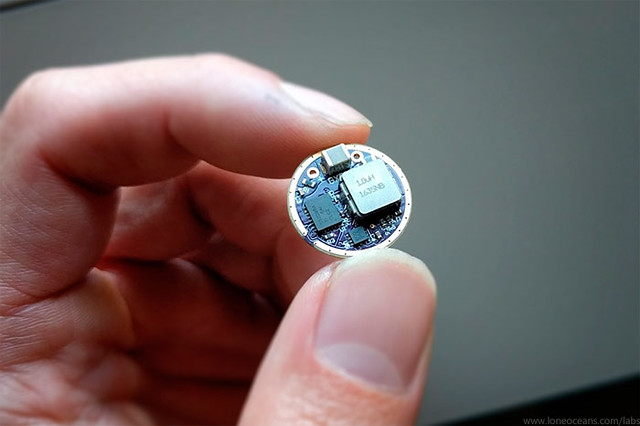
PCB Assembly and Flashlight Build
Assembling the PCB
With the PCB layout done, I sent the boards for
fabrication. To handle the increased power levels, I opted for 2oz
copper instead of the usual 1oz.
Due to the very small size of the board, assembly was
done with a combination of optical magnification, small soldering iron,
tweezers, hot air, as well as a good regular soldering iron for the
larger components.
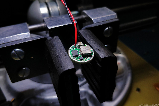
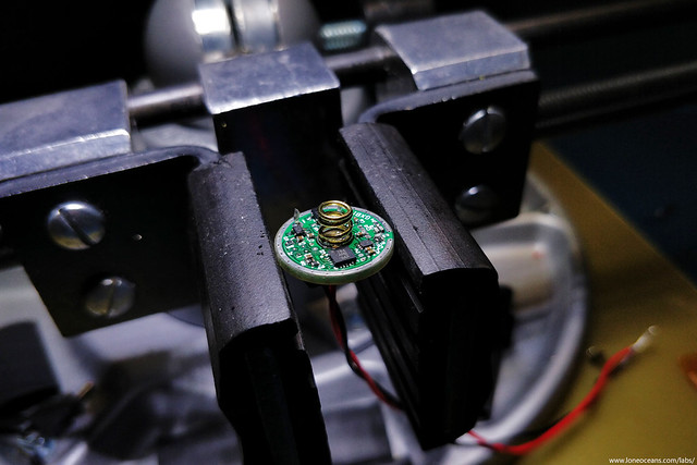
Fortunately the board came together without too much
difficulty - but I suspect for most hobbyists, this will be a very
challenging board to assemble! I managed to use all 0402 components,
except for two passives which had to be 0201. The ICs were a little more
challenging to solder on but everything was assembled in about an hour.
The board was then tested and verified to be working! :)
End 2017
18350 Flashlight Build
With the GXB17 driver verified to be working as intended, it was
time to put it inside a flashlight.
For this build, I knew I wanted a flashlight that would be
reliable enough for everyday use. I decided to go for a small run of
half-thickness but
2oz copper PCBs on OSHpark for better power
handling capabilities, lower inductances and better thermal
dissipation. This new board was soldered up as shown above.

The flashlight host of choice was the venerable
Convoy S2+ which
is often available for just about $10 or so. Convoy is one of
the most popular brands of fairly high quality flashlights. They
are based in China, and over the years, have produced not only
excellent flashlights, but have also taken their customer
feedback very seriously and keeping quality fairly very high. The S2
line is one of their most popular, and designed around a single
18650-cell, a 17mm driver, and a 16mm LED PCB.
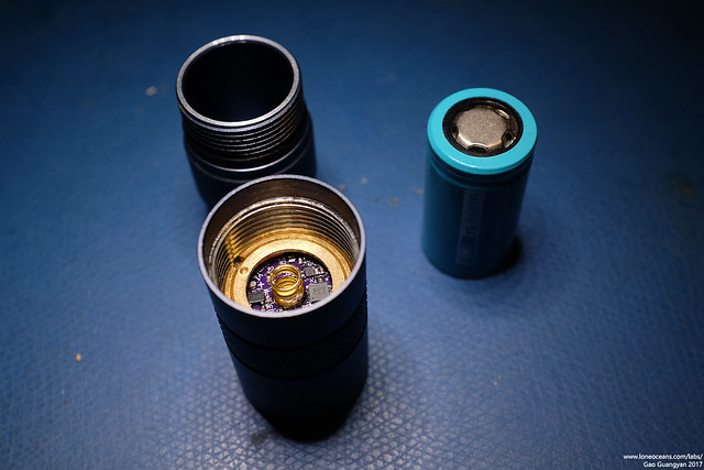
Before putting the driver into the flashlight, I made sure it
would fit into the pill. The driver fits perfectly, but I
wasn't very comfortable with how close the threaded retaining ring
was getting to some of the components (since it presses down on
the edges to keep the board in place), so I soldered ring of
copper wire around the edge carefully as a little edge 'riser'.
A 5mm gold-plated steel
spring was also installed as the battery spring. For wires, 22AWG Teflon wire was used
for its high temperature rating. I could probably use a thicker
wire gauge but 22 AWG is more than sufficient since the wire
lengths will be very short.
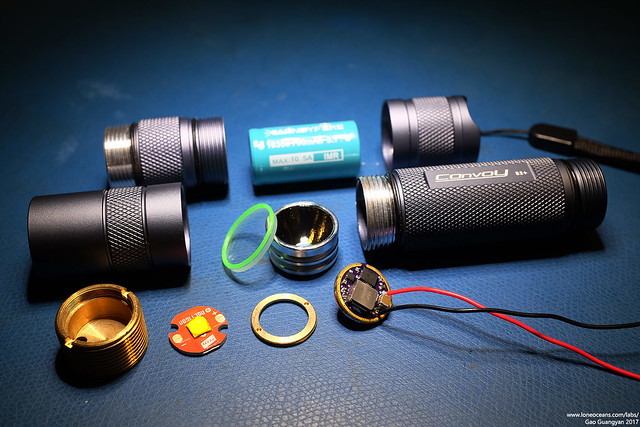
Once the driver was ready, it was time to put the flashlight
together. Here's the Convoy S2+ light taken apart and ready for
assembly.
One fun aspect of the Convoy S2+ (and due to its popularity) is
that it comes with several modifiable and swappable parts! I
thought it would be fun to have a 2000 lumen flashlight in an
ultra-small body, so I bought a shorter body tube, as well as a
18350 battery to go along with it. This reduces the overall
flashlight length by 30mm, though at the cost of reduced runtime
from the smaller battery. But that's ok - that's what the
flashlight modes are for!
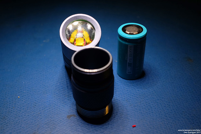
For the LED, I opted this time for a
XHP50B J4-class 5700K 6V LED mounted on
a 16mm Noctigon copper-core PCB. This powered with the GXB17
driver and a
Windyfire 18350 700mAh lithium cell should give a very
bright yet small flashlight! Unfortunately at time of
construction (end 2017), I was still unable to get any high-CRI
XHP50B LEDs, so instead we'll go for a bright but lower CRI one.

The driver fits right in comfortably.
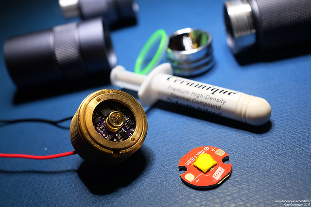
For the LED PCB, a tiny amount of Arctic
Silver Ceramique thermal paste was used for better thermal
contact between the MCPCB and the brass pill. The driver wires were
then soldered on with a very hot soldering iron. The pill
was then assembled into the front assembly, which features a beautiful
orange-peel reflector.
It's a little odd and surprising to see such a large LED in such
a small flashlight, and even more surprising to see how much
light it can put out! :)
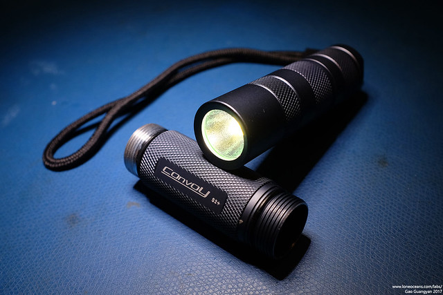
Above, the GXB17 in action powered with a single 18350,
The GXB17 project is a success! It
took a while to get to this point, starting from the GXB20, the
GXB20 revision and now the GXB17, so it was great to finally be
able to see the GXB17 used as it was originally designed!
Results
End 2017
18350 Convoy S2+ Build and Comparison
The goal of the GXB17 project was to achieve creating a
very compact flashlight capable of producing a very bright, high-quality
light, while also being a sensible light which I can use for everyday
purposes.
Let's see how it stacks up in real life by comparing our 'shorty'
S2+ GXB17 build with some other existing lights I have.

Above shows the size comparison of the completed
flashlight when compared to some benchmarks.
From left to right:
9V battery, AA battery, GXB17 18350 build in a short Convoy S2+,
standard 18650 Convoy S3 flashlight with Cree XM-L2 U2-1A T6 4C 7135x6
driver, Ultrafire SK98 light with GXB20 driver, and finally the same but
with the lens zoomed out.
Ass you can see, the GXB17 allows a much smaller build
than my SK98 build, but with the potential of even better light output (due to the much more efficient reflector
design vs. the zoomy lens design of the SK98).

Above shows the 'shorty' Convoy S2+ 18350 build, as compared to a
regular-length Convoy S3 18650 flashlight.
Informal test with Lightmeter app on my phone
As a informal test (this is definitely not meant to be
scientific in any way) to get some numerical values, I decided to obtain
some lux readings in my room using my phone. The test is as follows. I
used my phone's Lightmeter app. The phone was placed on the ground near
the middle of the room, with the screen facing straight up. The lights
in the room were switched off, and the following flashlights/light
sources were used to illuminate the room. This was done by pointing the
light directly up to the ceiling (featureless), near the phone.
Batteries were fully charged before each test, and the test was repeated
several times. The values were found to be extremely consistent, all
within 1 value of each previous reading!
| Illumination Device |
Description |
Illuminance (Lux) |
| 9W 3000K Greenlite LED Bulb |
Rated at 800 lumens, regular light bulb |
14 Lux |
| 15W 5000K Cree LED Bulb |
Rated at 1700 lumens, regular light bulb |
38 Lux |
|
Convoy S3 with 6x 7135 driver at max brightness |
XML2 T6-4C (4300-4500K) LED / Lithium ion 18650 LGDBHE21865
Battery - calculated at 750 lumens from datasheet at 2.1A drive |
50 Lux |
| SK98 Zoomy at widest with GXB20 |
XHP50A G2-class 90CRI 4000K LED / Lithium ion 18650
LGDBHE21865 Battery - previously calculated at 1700 lumens from
datasheet at 22W |
102 Lux |
| Convoy S2+ shorty with GXB17 |
XHP50.2 J4-class 5700K LED / 700mAh Lithium ion Windyfire
18350 Battery |
137 Lux |
Obviously with light-bulbs having a large diffuser, we
can expect the lux values to be far lower since the bulbs light up the
whole room and not just the ceiling, and I only added them in the test
above for completeness. Bulbs were on with no lamp shade.
So let's look at the flashlights. The XHP50A and 50B
brightness bin values seem to be the same according to the datasheet, so right
off the bat even with the same drive power, we expect the J4-class 50.2
LED used in the GXB17 build
to be brighter, and the results do show that! This could be further
exacerbated by the fact that the SK98 has a more lossy front end with the optics and no reflector,
though I don't really have any way to verify this numerically yet. The GXB17
light in this configuration is almost 30% brighter!
So supposing the general reflector properties are the
same between the Convoy S3 and S2+, we can then extrapolate the lux
values, and conclude that the GXB17 is indeed putting out all the
ballpark of ~2055 lumens of light! Again this is in no
way a controlled test, but it does give a general idea on the brightness
and efficacy of the GXB17 driver in a S2 host.
Beam-shots
Now let's see some beam shots to have a good idea of how
they look like in real life.
For this simple comparison test, I set up a GXB20
in a SK98 light, the Convoy S3 light, and the GXB17 in a Convoy S2 at the same location. Photos
were taken with my camera on manual, set to a fixed 400 ISO, aperture
f6.3, WB set
to sunlight mode, and a fixed 1/60s exposure. You can just about make
out the blurred outline of the flashlight at the centre bottom of each
photo.

Here are the results. What's most interesting to me is
the different beam profiles of the Convoy orange-peel reflectors vs. the
lens optic on the SK98, as well as what a huge difference high and low
CRI lighting results in, with the 90CRI LED putting out a much nicer
colour!
For brightness, note the white bear in the center of the photo -
the GXB17 is really putting out a massive amount of light! .. though I
might have to change that LED out for a >90CRI one soon!
July 2017
Firmware, Modes and Real Life Usage
Since the design is basically the same as the GXB20
V2,
the same firmware can also be used on the GXB17. The firmware for the
GXB17 was
completed in July 2017.

The GXB20 V2 firmware ported over to the GXB17 with minimal
modification.
The above flowchart shows the general operating states
along with error and fault conditions.

Testing and firmware development was done with a bench power supply, and a
XHP50A-00-0000-0D0UG20E2 LED configured for 6V operation, mounted on a
large heat-sink as shown above. Power output was essentially identical
to the GXB20; exactly as expected! :)
Useful Links
References and Links
BudgetLightForums - Thread of this project
on BLF as it progressed
Cree XHP50.2 - The next generation Cree XHP50B LEDs
Convoy
Flashlights - Official Convoy shop on Aliexpress
TPS61088 - 10A
fully integrated synchronous boost converter
TPS61178 - 20V
fully integrated synchronous boost converter with load
disconnect
Back to main page
(c) Gao Guangyan 2025
Contact: loneoceans [at] gmail [dot] com |

